T568A vs T568B Wiring: RJ45 Pinout, Color Code & Diagram (2026)
T568A and T568B are two RJ45 wiring standards defined by TIA/EIA-568. The only physical difference is that pins 1–2 and pins 3–6 swap the green and orange pairs. Both have identical electrical performance and both support Gigabit, 10G, and PoE. Use T568B for most commercial installations and T568A for U.S. residential or government projects — but the most important rule is to use the same standard on both ends of the cable.
| Feature | T568A | T568B |
|---|---|---|
| Pin 1–2 pair | White-Green / Green | White-Orange / Orange |
| Pin 3–6 pair | White-Orange / Orange | White-Green / Green |
| Pin 4–5 pair | Blue / White-Blue | Blue / White-Blue |
| Pin 7–8 pair | White-Brown / Brown | White-Brown / Brown |
| Primary use | U.S. residential, government, USOC backward compat | Commercial, enterprise, ISP, most installs worldwide |
| Compatible with Cat5e/6/6a | Yes | Yes |
| Supports PoE / PoE+ / PoE++ | Yes | Yes |
| Supports 1G / 2.5G / 10G | Yes | Yes |
| Electrical performance | Identical | Identical |
T568A vs T568B — side-by-side comparison
RJ45 (Registered Jack 45) is the 8-pin connector used at both ends of an Ethernet cable to link PCs, switches, routers, access points, and other devices in modern networks. For example, many enterprise deployments rely on Cisco Catalyst access switches terminated with RJ45 patch cords. The way the 8 conductors inside the cable are arranged in that RJ45 plug is defined by two TIA/EIA wiring standards: T568A and T568B.
This guide covers the T568A vs T568B pinout, the RJ45 color code for each, when to choose which, the difference between straight-through and crossover cables, and a step-by-step crimping walk-through.
What Is an RJ45 Connector?
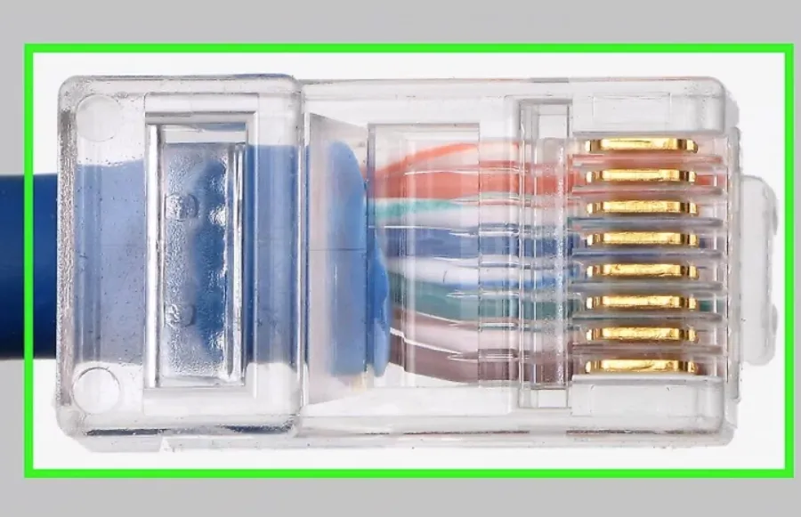
An RJ45 plug (“crystal head”) is a small plastic connector with 8 metal pins that bite into the 8 conductors of a twisted-pair cable when crimped. Clean, reliable contact between the pins and the conductors is what makes Gigabit, 10G, and PoE work over copper.
Twisted-pair cables come in two forms: UTP (Unshielded Twisted Pair) for general office and home Ethernet, and STP (Shielded Twisted Pair) for environments with heavy EMI (industrial floors, near power cables, data centers). Inside the jacket, the 8 conductors follow a fixed color scheme — white-orange, orange, white-green, blue, white-blue, green, white-brown, brown — and the T568A/T568B standards tell you which color goes on which pin.
What Is T568A? (Pinout & Color Code)
T568A is one of the two RJ45 wiring standards defined by ANSI/TIA-568. It places the green pair on pins 1 and 2 and the orange pair on pins 3 and 6. T568A is preferred in U.S. residential cabling and is required by some U.S. government and federal projects because it is backward-compatible with the older USOC one-pair and two-pair telephone wiring.
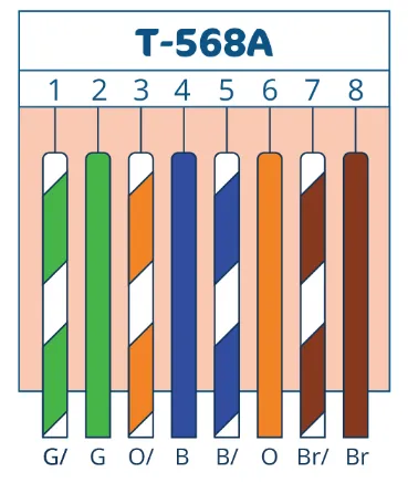
T568A RJ45 pinout (pin 1 on the left when the clip faces away from you)
T568A Color Code (Pin Order)
- Pin 1 — White-Green
- Pin 2 — Green
- Pin 3 — White-Orange
- Pin 4 — Blue
- Pin 5 — White-Blue
- Pin 6 — Orange
- Pin 7 — White-Brown
- Pin 8 — Brown
What Is T568B? (Pinout & Color Code)
T568B is the other RJ45 wiring standard from ANSI/TIA-568, and it is the most widely used standard in commercial, enterprise, and ISP installations worldwide. It puts the orange pair on pins 1 and 2 and the green pair on pins 3 and 6 — the exact opposite of T568A on the first two pairs. T568B descends from the older AT&T 258A specification, which is why it became dominant in business cabling.
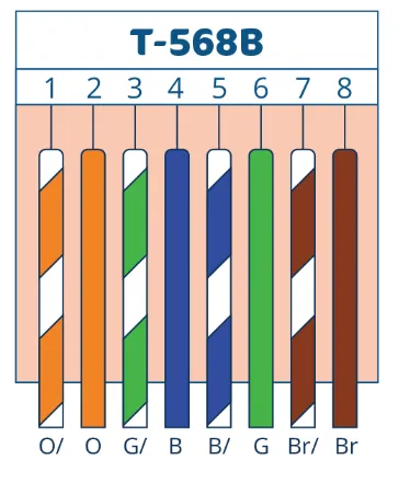
T568B RJ45 pinout — the most common wiring standard in commercial Ethernet
T568B Color Code (Pin Order)
- Pin 1 — White-Orange
- Pin 2 — Orange
- Pin 3 — White-Green
- Pin 4 — Blue
- Pin 5 — White-Blue
- Pin 6 — Green
- Pin 7 — White-Brown
- Pin 8 — Brown
T568A vs T568B: Key Differences and Which One to Use
The only physical difference between T568A and T568B is that the green and orange pairs are swapped on pins 1–2 and 3–6. Pins 4, 5, 7, and 8 are identical in both standards. Electrically, the two are 100% equivalent — the same Cat5e or Cat6 cable will deliver the same speed, the same PoE wattage, and the same signal quality regardless of which standard you pick.
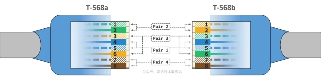
T568A vs T568B side-by-side — only pins 1, 2, 3, and 6 differ
When to Choose T568A
- U.S. residential installations (recommended by TIA for new homes)
- U.S. federal government contracts where T568A is specified
- Sites that need backward compatibility with USOC 1-pair/2-pair telephone wiring
- Existing facilities already standardized on T568A
When to Choose T568B
- Commercial, enterprise, and data-center cabling — by far the most common choice
- ISP and carrier installations
- Most patch cords sold pre-terminated worldwide (they’re wired T568B)
- Mixed environments where you need to match existing T568B infrastructure
The single most important rule: pick one standard and stick with it across your entire site. Mixing T568A and T568B on the two ends of the same cable creates a crossover cable, which is rarely what you want on a modern network.
Straight-Through vs Crossover Cable (T568A and T568B in Practice)
Whether your finished Ethernet cable is a “straight-through” or a “crossover” depends entirely on whether the two ends use the same standard or different ones:
| Cable type | End A | End B | Used for |
|---|---|---|---|
| Straight-through | T568B | T568B | PC↔switch, switch↔router, AP↔switch (default) |
| Straight-through | T568A | T568A | Same as above — residential/government variant |
| Crossover | T568A | T568B | Legacy PC↔PC, switch↔switch (uplink) before Auto-MDIX |
Modern switches and NICs support Auto-MDI/MDIX, which detects the cable type automatically and re-pairs internally. As a result, crossover cables are almost never needed today — when in doubt, make a straight-through cable using T568B on both ends.
How to Make an RJ45 Ethernet Cable (T568A or T568B)
Tools and materials: RJ45 plugs, twisted-pair cable (Cat5e, Cat6, or Cat6a), a crimping tool, a wire stripper, and a cable tester.
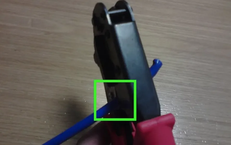
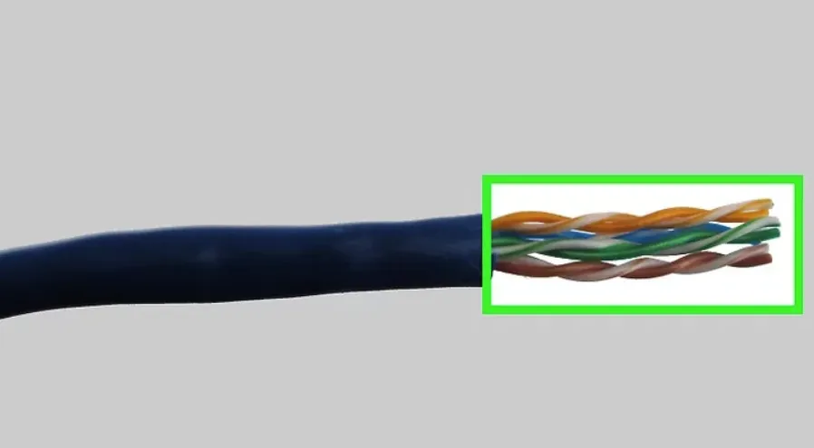
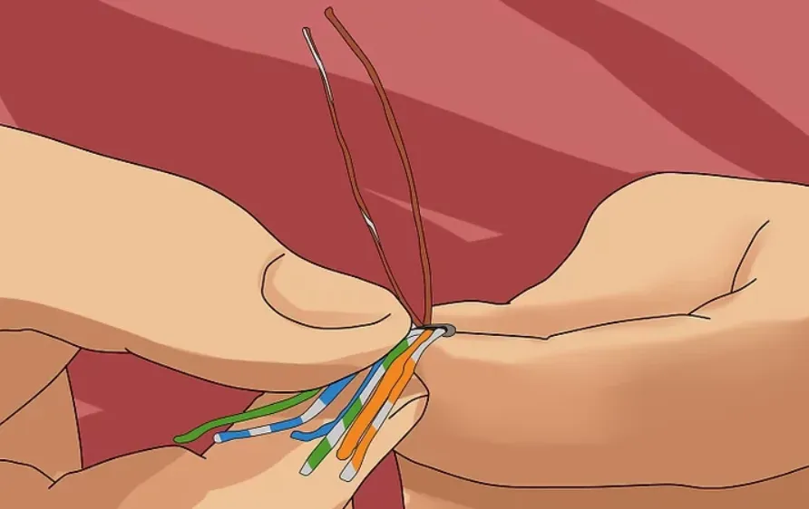
Step 1: Strip the Jacket and Untwist the Pairs
Strip about 25–30 mm (1 inch) of the outer jacket to expose the 4 twisted pairs. Untwist each pair only as much as needed to align them — keeping the twists close to the plug preserves crosstalk performance.
Step 2: Arrange the Wires (T568A or T568B Order)
Flatten the 8 conductors side by side and order them according to your chosen standard:
- T568B (most common): White-Orange, Orange, White-Green, Blue, White-Blue, Green, White-Brown, Brown
- T568A: White-Green, Green, White-Orange, Blue, White-Blue, Orange, White-Brown, Brown
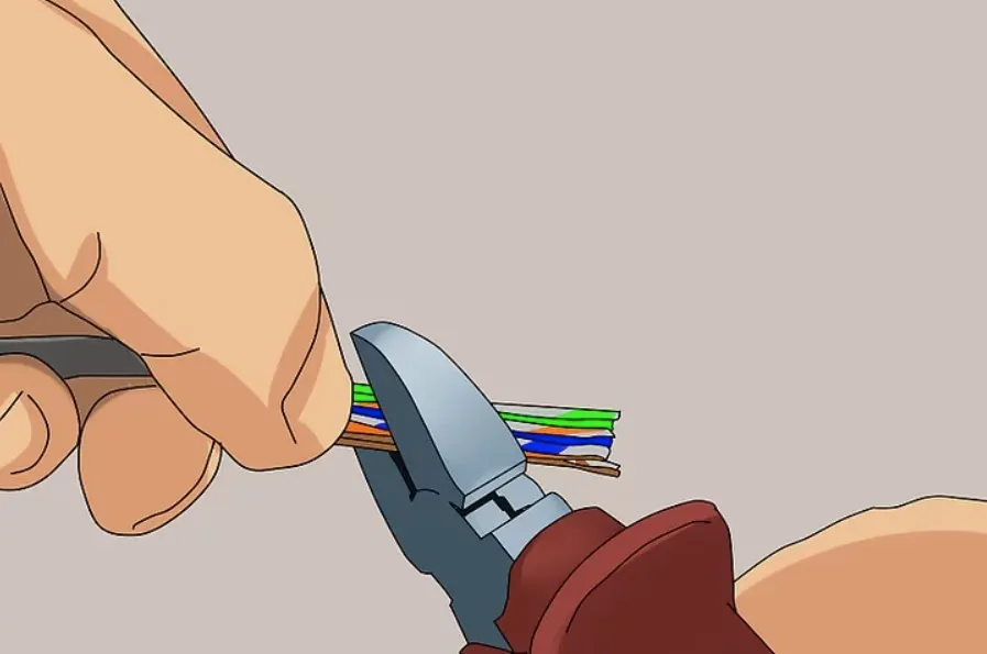
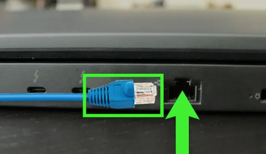
Step 3: Trim and Insert Into the RJ45 Plug
Trim the conductor ends flat so they’re all the same length, then insert them firmly into the RJ45 plug with the clip facing down. Each wire must slide fully into its channel and reach the metal contact at the front of the plug. The outer jacket should extend inside the plug so the strain relief grips it during crimping.
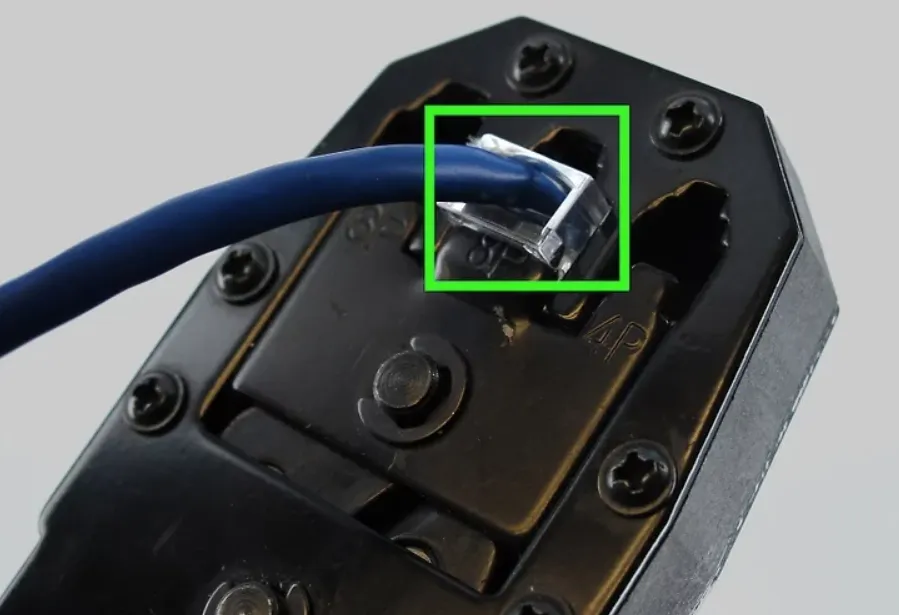
Step 4: Crimp the Plug
Place the loaded plug into the crimping tool and squeeze firmly until you feel and hear the contacts seat. This pushes the 8 metal pins through the insulation of each conductor and locks the jacket in the strain relief.
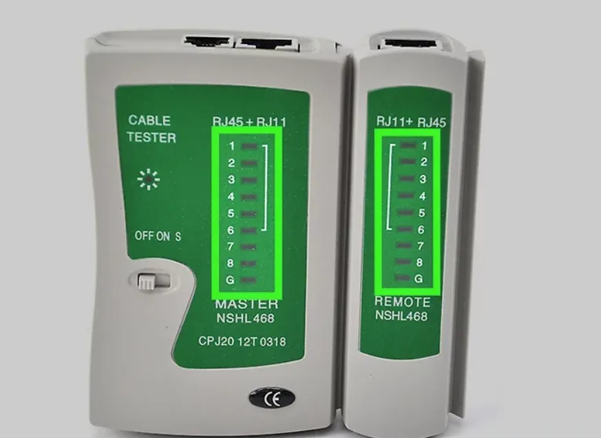
Step 5: Test the Cable
Plug both ends into a cable tester and confirm that all 8 pins light up in sequence (1→1, 2→2, … 8→8) for a straight-through cable. Any open, short, or miswire shows immediately — re-crimp before deploying.
FAQs: T568A vs T568B
What is the difference between T568A and T568B?
Both are TIA/EIA-568 RJ45 wiring standards with identical electrical performance. The only difference is that the green and orange pairs are swapped on pins 1–2 and pins 3–6. T568A puts white-green/green on pins 1–2; T568B puts white-orange/orange on pins 1–2.
Should I use T568A or T568B?
Use T568B for commercial, enterprise, and most modern installations — it is the global default. Use T568A for U.S. residential or federal-government projects that require it, or to match existing T568A infrastructure. Whichever you choose, use the same standard on every drop and every patch panel.
Is RJ45 A or B better?
Neither is technically better. T568B is more common (you’ll find it on almost all pre-made patch cords and commercial installs); T568A is backward-compatible with older USOC telephone wiring and is preferred for U.S. residential cabling. Performance for Gigabit, 10G, and PoE is identical.
What happens if you use T568A on one end and T568B on the other?
You create a crossover cable — pins 1–2 and 3–6 are swapped between the two ends. This was once needed for PC-to-PC or switch-to-switch links. Modern switches and NICs support Auto-MDI/MDIX, so a crossover cable is rarely required today.
Does T568A vs T568B affect Cat5e, Cat6, 10G, or PoE performance?
No. Speed and PoE depend on the cable category (Cat5e / Cat6 / Cat6a), the length, and the quality of the termination — not on which TIA standard you choose. T568A and T568B both fully support 1G, 2.5G, 5G, 10G, and PoE++ (90 W).
What is the T568B color code in order?
From pin 1 to pin 8: White-Orange, Orange, White-Green, Blue, White-Blue, Green, White-Brown, Brown.
What is the T568A color code in order?
From pin 1 to pin 8: White-Green, Green, White-Orange, Blue, White-Blue, Orange, White-Brown, Brown.
How do I verify the RJ45 pinout after crimping?
Use a cable tester to confirm pin-to-pin continuity (1↔1, 2↔2, …, 8↔8 for straight-through). Check that the clip is on the correct side, follow the color code exactly, and re-crimp any pair that fails. A loose conductor or one that didn’t reach the contact is the most common cause of a failed test.
Related reading: