MLAG High Availability Explained – How Link Aggregation Plus Works
In modern enterprise and data center networks, high availability and zero downtime are non-negotiable requirements.
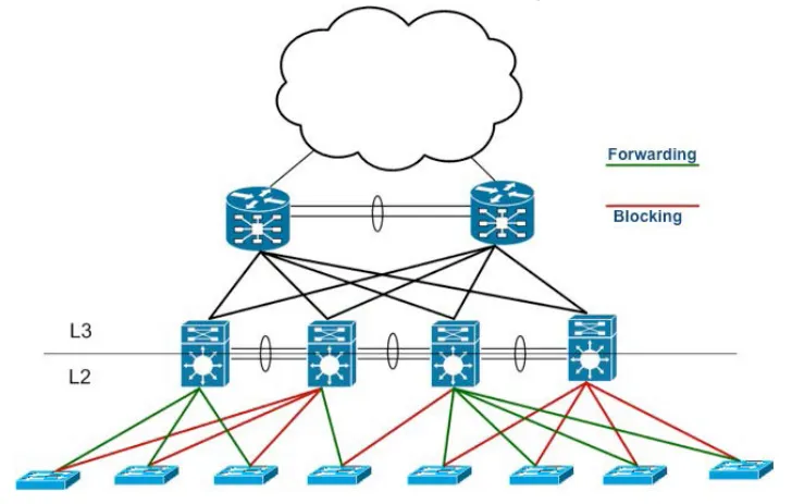
While traditional LACP-based link aggregation provides redundancy at the interface level, it cannot eliminate the single-switch failure point.
This is where MLAG (Multi-Chassis Link Aggregation) — also known as Link Aggregation Plus (LAG+) — comes in.
MLAG allows two switches to act as one logical device, providing both link-level and device-level redundancy.
This article explains how MLAG works, its architecture, and how it enhances network resilience.

What Is MLAG (Multi-Chassis Link Aggregation)?
MLAG is an advanced link aggregation technology that enables a device (such as a server or switch) to connect to two independent switches simultaneously.
To the connected device, these two switches appear as a single logical system.
If one switch or link fails, traffic automatically flows through the other without interruption.
Core benefits of MLAG:
- Device-level redundancy: Eliminates single-switch failure points.
- Active-active forwarding: Both switches forward traffic simultaneously.
- No blocked links: Unlike STP, all links are active and utilized.
- Faster convergence: Rapid recovery from link or node failures.
- Improved scalability: Supports seamless network expansion.
? Related reading: Link Aggregation Explained – LACP, Static vs Dynamic, and MLAG Guide
How MLAG Works
MLAG relies on synchronization and coordination between two peer switches.
Each peer maintains the same MAC address table, VLAN configuration, and control plane information to behave as a unified system.
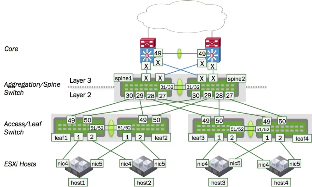
Key Components
- Peer-Link:
A dedicated inter-switch link used to synchronize state and control information between MLAG peers.
It carries traffic when one of the member links fails. - Peer-Keepalive Link:
A separate link used solely for heartbeat messages.
It ensures that each switch knows whether the peer is alive, helping to prevent split-brain scenarios. - MLAG Domain:
The logical grouping that defines the MLAG peers, the peer-link, and participating interfaces. - Member Interfaces:
These are the physical ports connecting to downstream devices, forming the MLAG trunk.
MLAG vs Traditional LACP
|
Feature |
Traditional LACP |
MLAG (Link Aggregation Plus) |
|---|---|---|
|
Aggregation Scope |
Within a single switch |
Across two switches |
|
Redundancy |
Link-level only |
Link-level + device-level |
|
STP Interaction |
Some links may be blocked |
All links active |
|
Failover Time |
1–3 seconds |
< 1 second |
|
Scalability |
Limited to one chassis |
Supports multi-switch domains |
MLAG extends the benefits of LACP to a multi-device scenario, combining redundancy, load balancing, and high availability in one architecture.
MLAG Operational Principles
Step 1: Peer Establishment
Both switches form an MLAG peer relationship using the peer-link and peer-keepalive connections.
Step 2: Configuration Synchronization
MAC tables, VLAN IDs, and port states are synchronized between peers to ensure identical forwarding behavior.
Step 3: Active-Active Forwarding
Downstream devices (servers, access switches) see both peers as a single logical switch.
Traffic is distributed across both sides for load balancing.
Step 4: Failure Handling
If one switch or link fails, its traffic is automatically redirected through the remaining peer, with almost zero downtime.
Huawei and Cisco MLAG Implementation
On Huawei Devices (Eth-Trunk + M-LAG)
Huawei implements MLAG through its Eth-Trunk + M-LAG mechanism.
Each member switch runs a peer-link and a peer-keepalive session to maintain synchronization.
<HUAWEI> system-view
[HUAWEI] m-lag domain 1
[HUAWEI-m-lag-domain1] source-address 10.10.10.1
[HUAWEI-m-lag-domain1] peer 10.10.10.2
[HUAWEI-m-lag-domain1] peer-link eth-trunk 10
[HUAWEI-m-lag-domain1] keepalive vlan 100
[HUAWEI] interface eth-trunk 1
[HUAWEI-Eth-Trunk1] mode lacp-static
[HUAWEI-Eth-Trunk1] m-lag 1
Explanation:
The M-LAG domain connects two switches via peer-link and keepalive VLAN to form a unified aggregation group.
On Cisco Devices (vPC / MLAG)
Cisco implements MLAG under the feature name vPC (Virtual Port-Channel).
It achieves the same goal — providing multi-chassis redundancy and active-active forwarding.
Switch# configure terminal
Switch(config)# feature vpc
Switch(config)# vpc domain 10
Switch(config-vpc-domain)# peer-keepalive destination 10.1.1.2 source 10.1.1.1
Switch(config-vpc-domain)# peer-link port-channel 1
Switch(config)# interface port-channel 2
Switch(config-if)# vpc 2
Explanation:
Two switches are paired as vPC peers, sharing a peer-link and keepalive connection.
Member ports (Port-Channel 2) provide dual-active connectivity to downstream devices.
Benefits of MLAG Deployment
- Zero Downtime Redundancy: No single point of failure between switches.
- Active-Active Load Balancing: Optimized bandwidth utilization.
- Fast Recovery: Failover in milliseconds, not seconds.
- Simplified Network Design: Removes the need for STP in access-core connections.
- Vendor Interoperability: Supported across Huawei, Cisco, Juniper, and Arista devices.
MLAG Use Cases
- Data Centers: Server uplinks and TOR-to-aggregation connections.
- Enterprise Core Networks: Dual-active redundancy between distribution and core layers.
- Cloud Platforms: Ensures service continuity in multi-tenant architectures.
- Industrial Automation: Provides uninterrupted connectivity for control systems.
Common MLAG Issues and Troubleshooting Tips
- Peer-Link Failure:
Always ensure a secondary keepalive link is active to avoid split-brain conditions. - Configuration Mismatch:
Verify VLAN, interface, and LACP settings are identical on both peers. - MAC Flapping:
Occurs when peers are unsynchronized — check peer-link health. - STP Loops:
Disable STP on MLAG-connected interfaces unless necessary for edge devices.
Best Practices for MLAG Deployment
- Keep peer-link and keepalive on separate physical paths.
- Ensure identical configuration on both peer devices.
- Use reliable monitoring tools for MLAG state and sync status.
- Combine MLAG with LACP for best load-balancing efficiency.
- Test failover before production deployment.
Conclusion
MLAG (Multi-Chassis Link Aggregation), or Link Aggregation Plus, extends the benefits of traditional LACP by providing both link-level and device-level redundancy.
It enables active-active forwarding, faster recovery, and full link utilization, making it the preferred solution for high-availability enterprise and data center networks.
By combining MLAG with best practices such as dual keepalive paths and configuration synchronization, you can achieve near-zero downtime and a truly resilient network infrastructure.