What Is an Uplink Port on a Switch?
An uplink port is the switch port that connects “up” to the next device in the network hierarchy — a distribution switch, core switch, or router — and carries the combined traffic of everything below it. “Uplink” is a role and a direction, not a special one-way or fiber-only kind of port. On a modern switch almost any port can act as one, but the port a vendor labels as the uplink is usually faster, is configured to carry every VLAN, and is sized so it does not become a bottleneck — the three details that actually decide whether the network runs cleanly or chokes.
Most explainers stop at “the uplink connects to another switch and is faster.” But whether an uplink actually performs comes down to three things they rarely mention: how it is sized against the traffic below it, why it is almost always a VLAN trunk, and why a second uplink does not add bandwidth unless you bond it.

What Is an Uplink Port?
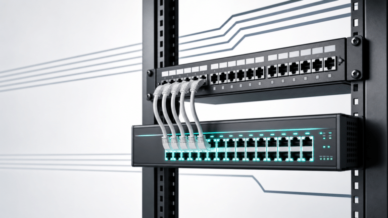
An uplink port is the connection a switch uses to reach the rest of the network. In a layered design, access switches sit closest to end devices and connect upward to distribution or core switches, which connect to routers and the internet. The port that carries traffic up that chain is the uplink, and its job is aggregation: a 48-port switch gathers the traffic of up to 48 devices and funnels it through one or two uplinks.
On a modern switch this is not a separate category of hardware. It is an ordinary switch port used for a specific role in the topology. That single fact — that “uplink” describes where a port connects, not what the port is — explains almost every question that follows.
Uplink Port vs Normal Port: What Actually Differs
A normal port (an access port) connects an end device — a PC, phone, access point, or camera. An uplink port connects the switch to other network gear. Most comparisons list only speed and media; the operational differences that actually matter are wider:
| Aspect | Uplink port | Normal (access) port |
|---|---|---|
| Connects to | Another switch, router, or core | A single end device |
| Direction in the topology | Up toward the higher tier | Down to the user (a downlink) |
| Typical speed | 10G / 25G / 40G (SFP+, QSFP) | 1G, or Multigigabit |
| Typical media | Fiber via SFP/SFP+ | Copper RJ-45 |
| VLAN configuration | 802.1Q trunk — carries all VLANs | Access — one VLAN |
| Usually supplies PoE? | No | Often, on a PoE switch |
The last two rows are where generic guides go quiet, and they are exactly where uplinks behave differently from access ports. An access port hands one VLAN to one device; an uplink almost always has to carry every VLAN to the rest of the network, which makes it a trunk. And PoE is delivered downward to powered devices, so the uplink is normally not a PoE source. Both points have real consequences, covered below.
Uplink and Downlink Ports Explained
Uplink and downlink are two views of the same connection, named by direction in the hierarchy. An uplink connects a device upward, toward a higher-tier switch or router. A downlink is the opposite view: from the higher switch looking down, the port that faces a lower switch or end devices is a downlink. In practice the “normal” access ports on a switch are its downlinks — they hand network access down to the devices that use it — while the port carrying everything up to the core is the uplink. The same cable is an uplink at the lower switch and a downlink at the upper one; which word applies depends on where you stand in the topology.
Does an Uplink Port Only Carry Upstream Traffic?
No. An uplink is not a one-way path. Ethernet links are full-duplex and bidirectional, so an uplink carries traffic in both directions at the same time: the upstream traffic from devices below it and the downstream replies coming back. When a user downloads a file, that data flows down through the same uplink the request went up through.
“Uplink” only tells you which device the link connects toward — the one that is “up” the hierarchy — not the direction data flows. This is also why the word appears in several places and confuses people:
- Switch uplink — a switch’s port to a higher-tier switch or router (the subject of this guide).
- Router or firewall “uplink” / WAN port — the port facing the internet provider.
- Server NIC uplink — a server’s network card connecting up to a switch, often teamed for redundancy.
- ISP uplink — the provider-side link out of your building.
All of them mean “the connection toward the upstream side.” None of them is a one-way card or a fixed traffic direction, so an “uplink NIC” or uplink port is not limited to outbound use.
Uplink Ports Are Trunk Ports: Carrying VLANs Upstream
Here is the part most “uplink port” articles skip entirely. If a switch carries more than one VLAN — and almost every business switch does — the uplink has to deliver all of those VLANs to the rest of the network. It does that as an 802.1Q trunk, which, in Cisco’s words, carries “the traffic of multiple VLANs over a single link.” An access port belongs to one VLAN; an uplink trunk tags frames so many VLANs share the one physical link.
One VLAN on a trunk is special: the native VLAN, which travels untagged and defaults to VLAN 1. This is where a quiet, painful failure lives. Cisco’s documentation states that you must keep the native VLAN the same on both ends of a trunk, because mismatched native VLANs can result in spanning-tree loops — and a native-VLAN mismatch also lets traffic “leak” between two VLANs that were supposed to stay separate. If you have ever seen two switches that link up but behave strangely, a native-VLAN mismatch on the uplink is a prime suspect. (For the difference between VLAN 1, the default VLAN, and the native VLAN, see our default VLAN vs native VLAN guide.)
Practical rule: configure the uplink as a trunk, set the same native VLAN on both ends, and allow only the VLANs that actually need to cross it.
How to Size an Uplink: Oversubscription Math
Because the uplink is shared by every device on the switch, the question that matters is not “is it fast?” but “is it fast enough for the load below it?” The metric is oversubscription — the ratio of total access bandwidth to uplink bandwidth.
Take a 48-port gigabit switch. If every access port could run flat out, that is 48 Gbps of potential demand. Pair it with two 10G uplinks (20 Gbps) and the ratio is 48:20, about 2.4:1 — comfortable, because real devices rarely all burst at once. Pair the same switch with a single 1G uplink and the ratio is 48:1 — a severe choke point that will collapse under load.
| Access ports | Uplink | Oversubscription | Verdict |
|---|---|---|---|
| 48 × 1G | 1 × 1G | 48:1 | Severe bottleneck |
| 24 × 1G | 2 × 1G | 12:1 | Borderline |
| 48 × 1G | 2 × 10G | ~2.4:1 | Comfortable |
| 48 × Multigig (2.5G) | 2 × 25G | ~2.4:1 | Comfortable |
How much oversubscription is acceptable? Cisco’s campus design guidance gives a rule of thumb of roughly 20:1 at the access-to-distribution uplink and 4:1 from distribution to core, noting that the higher the ratio, the higher the chance of transient congestion when many devices transmit or receive at the same time. Most access switches land well inside 20:1 with a pair of 10G uplinks; the failure mode is almost always under-provisioning the uplink, not the access ports.
Why Uplink Ports Are Usually Faster
This is the real reason uplinks run at 10G, 25G, or 40G while access ports sit at 1G: the uplink aggregates everything below it, so it needs more headroom to keep the oversubscription ratio sane. But the speed is a consequence of the aggregation role, not the definition of an uplink. A port is not an uplink because it is fast; it is an uplink because of where it connects. A 10G port feeding a single server is an access port, and a same-speed link between two switches is still an uplink.
Redundant Uplinks: Why Two Is Not Automatically Double
Switches often expose two uplinks, and it is easy to assume two uplinks mean twice the bandwidth. They usually do not — unless you configure them to.
- One uplink is a single point of failure. If that link, its optic, or the upstream switch fails, the whole access switch is isolated.
- Two plain uplinks create a loop, and spanning tree (STP/RSTP) responds by blocking one of them. You get failover — if the active link drops, the blocked one takes over — but the second link sits idle, so you do not get extra bandwidth.
- To use both at once, bond them. Link aggregation (LACP, the IEEE 802.1AX standard) combines two uplinks into one logical link with their throughput added together and automatic failover if a member drops. Cisco implements this as EtherChannel, and cross-stack EtherChannel spreads the bundle across different members of a switch stack, so an entire member switch can fail and the uplink survives.
The takeaway: for resilience, two uplinks to two upstream devices; for resilience and bandwidth, bond them with EtherChannel/LACP. Two unbonded uplinks give you a backup, not a bigger pipe.
Can a Regular Port Be Used as an Uplink?
Yes. Electrically, any switch port can serve as an uplink — connect it to another switch and it is one. Older equipment needed a dedicated uplink port or a crossover cable; modern Auto-MDIX removed that, so any port works with a standard straight-through cable.
The practical caveat is the oversubscription math above. In practice, the most common misstep we see is linking two busy switches through a spare 1G access port — it works, the lights turn green, and it quietly caps the entire path at 1G. That is why switches still ship with dedicated, higher-speed uplinks: not because a regular port cannot uplink, but because a faster one usually should. The reverse is also fine — an uplink port can serve an end device if you need it to, subject to the media (an SFP slot needs the right module).
Cisco Uplink Ports: Fixed vs Modular Network Modules
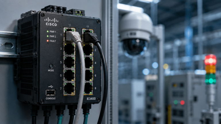
On Cisco switches, an “uplink port” is not a separate port type either. Smaller models build the uplinks in as a fixed set of SFP/SFP+ ports; larger ones take swappable uplink network modules so you can choose the uplink speed and media and upgrade later.
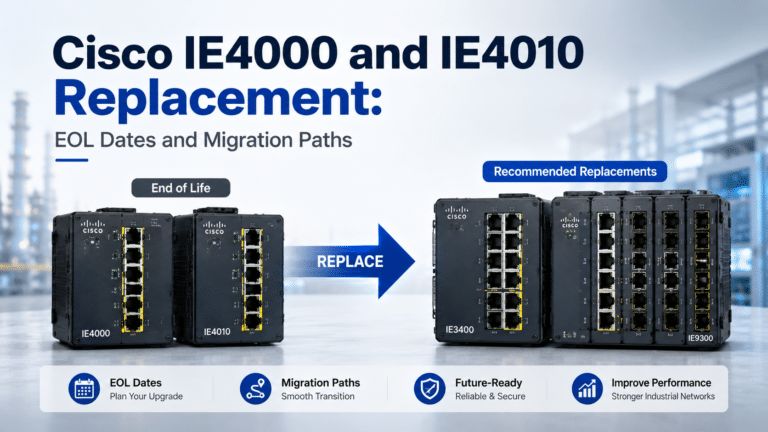
The Cisco Catalyst 9300 series is the clearest example. It accepts field-replaceable uplink Cisco Catalyst 9300 network modules that span 1G to 40G:
| Network module | Uplink ports |
|---|---|
| C9300-NM-4G | 4x 1G SFP |
| C9300-NM-4M | 4x Multigigabit copper |
| C9300-NM-8X | 8x 10G/1G SFP+ |
| C9300-NM-2Y | 2x 25G/10G/1G SFP28 |
| C9300-NM-2Q | 2x 40G QSFP+ |
Because the module is removable, a Cisco Catalyst 9300 switch can migrate its uplinks from 10G toward 25G and 40G — and on the Catalyst 9300X line, up to 100G — without replacing the chassis. Two procurement details catch buyers off guard: the default switch configuration does not include a network module, so the uplink module is ordered separately; and the module you pick sets your future oversubscription headroom, so it is worth choosing against the sizing math above rather than by habit.
Do Uplink Ports Supply PoE?
Generally, no. Power over Ethernet is delivered on the access/downlink copper ports to power end devices such as phones, access points, and cameras. Uplink ports connect to other switches or routers that have their own power, so they do not need PoE — and a fiber uplink cannot carry power at all. On a PoE switch, the PoE budget is reserved for the access ports; the uplinks move data only. Always confirm a specific model’s behavior, but planning a PoE device onto an uplink is the wrong assumption.
Uplink Cabling: Auto-MDIX, Crossover, and Fiber
The cabling question is mostly historical. Older switches wired the uplink port differently (MDI) from normal ports (MDI-X) so two switches could be joined with a straight-through cable, or you used a crossover cable between two normal ports. Auto-MDIX ended that: the switch detects the cable and adjusts automatically, so a straight-through cable works on any port, and crossover cables are effectively obsolete for switch-to-switch links.
For a fiber uplink, the “cable” is the SFP/SFP+ module plus its fiber. Both ends must use the same fiber type and wavelength, and the transmit and receive strands must be matched — the same rules as any fiber link, and a common source of an uplink that “won’t come up.”
Common Uplink Mistakes From the Field
Most uplink problems are not hardware failures; they are the predictable mistakes below — each one a consequence of something earlier in this guide:
- A 1G access port used as the link between two busy switches. It works, but oversubscription quietly caps the whole path at 1G.
- Native VLAN mismatch on the trunk. Different native VLANs on the two ends can cause spanning-tree loops and let traffic cross between VLANs that should be isolated.
- A single uplink with no backup. One optic or upstream failure isolates the entire switch.
- Expecting two uplinks to double bandwidth. Two unbonded uplinks are blocked down to one by spanning tree; bond them with EtherChannel/LACP to use both.
- Mismatched fiber type or wavelength on the uplink optic. A multimode module on one end and single-mode on the other will not link.
- Forgetting the uplink module or optic in the BOM. On modular switches the network module ships separately, and an uplink with no transceiver is just an empty slot.
How to Find and Use a Switch Uplink Port
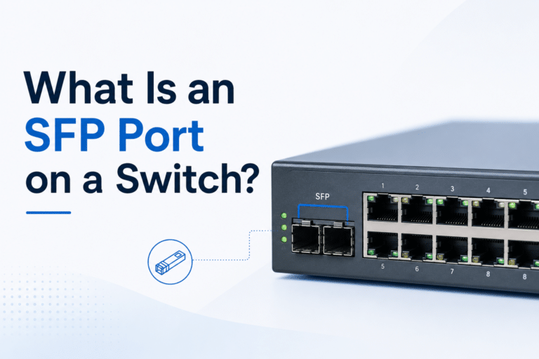
On most switches the uplink is easy to spot: it is the port labeled “uplink,” or the SFP/SFP+ ports set apart from the copper access ports, or simply the highest-speed ports on the unit. On a modular Cisco switch, it is the network-module slot rather than a fixed port. To use it: insert the right transceiver if it is an SFP/SFP+ slot — matching SFP and SFP+ uplink optics to your fiber type and distance — cable it to the upstream switch or router, configure it as a trunk if multiple VLANs cross it, and add a second bonded uplink where resilience or bandwidth demands it.
Frequently Asked Questions
Is an uplink port input or output?
Both. An uplink is a full-duplex Ethernet connection, so it sends and receives at the same time. “Uplink” describes the direction it connects in the network hierarchy — toward a higher-tier switch or router — not a one-way flow of data. Traffic moves up and down the uplink simultaneously.
Why do switches have two uplink ports?
For redundancy and, optionally, more bandwidth. A second uplink keeps the switch connected if the first link or upstream device fails. By default spanning tree blocks one of two uplinks to prevent a loop, so to use both at once you bond them with link aggregation (EtherChannel/LACP), which adds their throughput and still fails over.
Can I connect two switches using their normal ports?
Yes. Auto-MDIX lets you link two switches with a standard straight-through cable on ordinary ports — no dedicated uplink port or crossover cable. The reason to use the labeled uplink ports is their higher speed, which keeps the oversubscription ratio healthy when they carry the whole switch’s traffic.
Does an uplink have to be a VLAN trunk?
Usually, yes. If more than one VLAN needs to reach the rest of the network, the uplink must be an 802.1Q trunk so it can carry all of them on one link. If the switch only ever uses a single VLAN, the uplink can be a plain access port — but multi-VLAN networks need the trunk.
What is the difference between uplink and downlink?
An uplink connects a switch upward to a higher-tier device, such as a core switch or router. A downlink is the opposite direction — the higher device’s port facing down to a lower switch or to end devices. On a typical access switch, the user-facing access ports are downlinks and the port to the core is the uplink.
Is an uplink port the same as a trunk port?
No, but they usually overlap. “Uplink” describes a port’s role — it connects up to a higher-tier device — while “trunk” describes its VLAN configuration: it carries multiple VLANs using 802.1Q tags. An uplink is almost always configured as a trunk so every VLAN can cross it, but a trunk can also run between non-uplink ports, and an uplink that only carries one VLAN can be a plain access port.
Is the uplink port the same as the WAN port?
No. A WAN port, found on routers and firewalls, connects to an external network such as your internet provider. An uplink port connects switches inside your network to a higher tier. They sit at different points in the design — see our WAN vs LAN port guide for that distinction.