MSTP Protocol Explained: Multiple Spanning Tree in Depth
The MSTP protocol (Multiple Spanning Tree Protocol) is a variant of the spanning tree family that introduces the concept of multiple spanning trees. It was designed to overcome the limitations of STP and RSTP in large networks with many VLANs. This guide provides a detailed explanation of MSTP, including MST regions, CIST, IST, MSTI, topology calculations, and its relationship with VLANs.
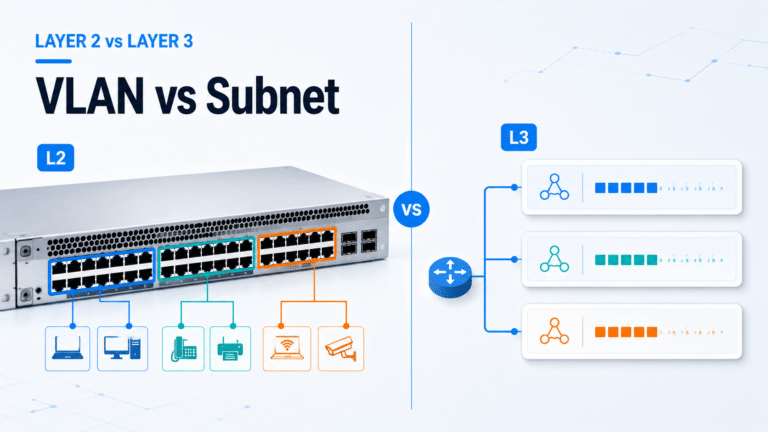
Before configuring instances and VLAN mappings, review the complete spanning tree comparison
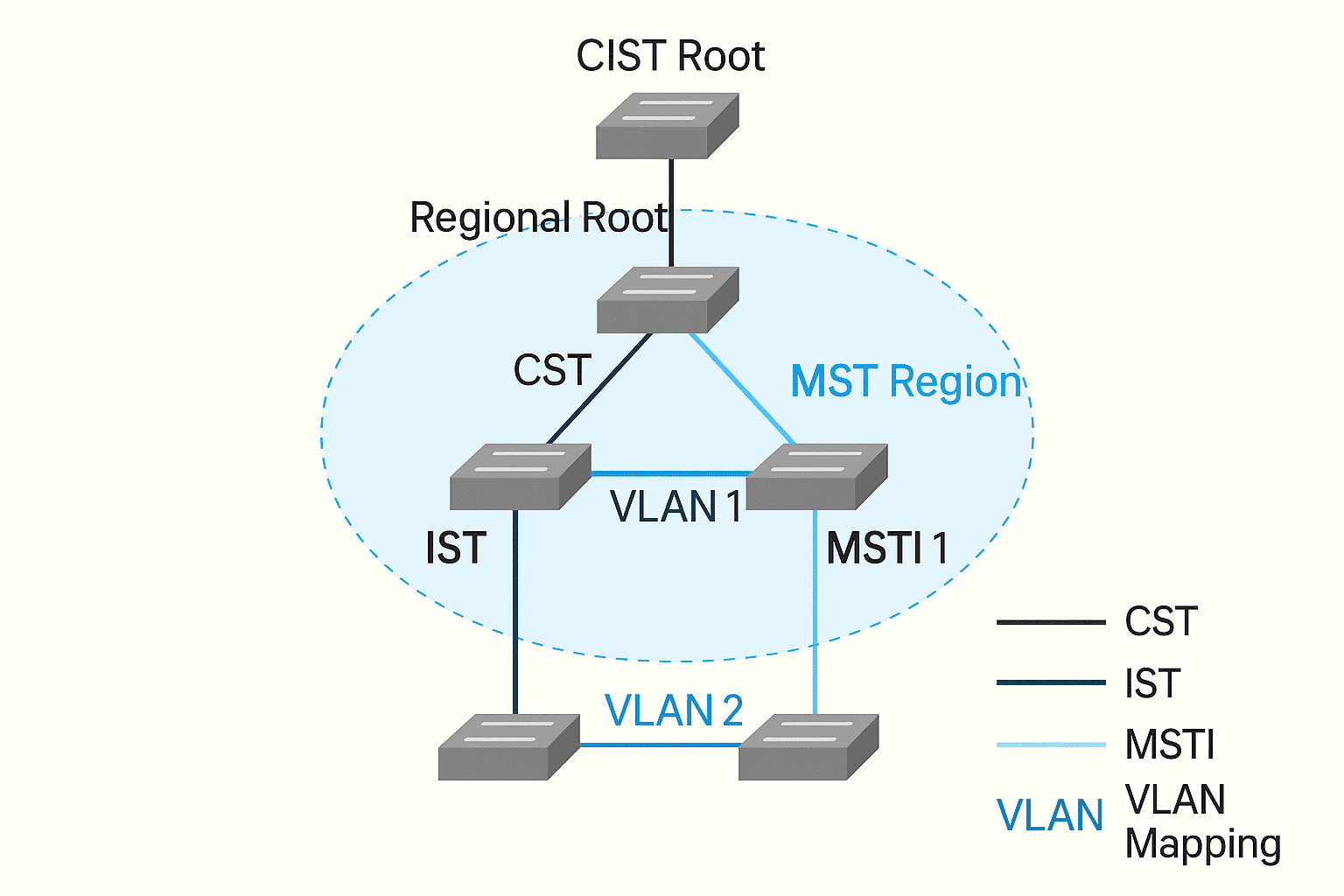
MST Region
An MST Region in the MSTP protocol is a group of devices and their interconnections that form a logically independent unit within an MSTP-enabled network.
To belong to the same MST Region, devices must meet the following conditions:
- MSTP Enabled: All devices must have MSTP enabled to participate in spanning tree calculations and maintenance.
- Same Region Name: All devices must share the same configured MST region name (a string identifier).
- Same VLAN-to-Instance Mapping: Devices must use the same VLAN-to-MSTI mapping, ensuring consistency in VLAN handling within the region.
- Same Revision Level: All devices must use the same MST revision level, which is incremented when the MST configuration changes.
A LAN can be divided into multiple MST regions. Regions may be directly or indirectly interconnected. Each region independently executes spanning tree calculations and maintains its own logical spanning tree.
CST, IST, CIST, and SST in MSTP
- CST (Common Spanning Tree)
CST is the spanning tree that connects all MST regions. Each MST region is treated as a single node. CST ensures loop-free connectivity across the entire network. - IST (Internal Spanning Tree)
IST is the single spanning tree within each MST region. Also known as MSTI0, IST is the internal representation of CIST inside a region. - CIST (Common and Internal Spanning Tree)
CIST is the single spanning tree calculated across the entire network using STP or RSTP. It includes both CST and IST, ensuring a unified loop-free topology. - SST (Single Spanning Tree)
SST occurs when devices run STP or RSTP with only one tree. In small cases, a single device can represent the entire spanning tree.
Regional Root, CIST Root, and Master Bridge
- Regional Root
- IST Root: The switch within an MST region closest to the CIST Root.
- MSTI Root: Each MST instance (MSTI) elects its own root within the region.
- CIST Root
The CIST Root is the root bridge of the entire network. For example, Device A could be elected as the CIST Root. - Master Bridge (IST Master)
The Master Bridge is the switch in a region closest to the CIST Root. If the CIST Root is inside the region, it also serves as the Master Bridge.
MSTP Topology Calculation
MSTP uses priority vectors to determine CIST and MSTI spanning trees.
Priority Vectors for CIST Calculation
- Root Bridge ID: Identifies the root for CIST.
- External Path Cost (ERPC): Cost from the regional root to the CIST root.
- Regional Root ID: Identifies the IST root within a region.
- Internal Path Cost (IRPC): Path cost from the local switch to the regional root.
- Designated Bridge ID: The bridge responsible for forwarding to the root.
- Designated Port ID: The port forwarding traffic toward the root.
- Receiving Port ID: The port that received the BPDU.
Priority Vectors for MSTI Calculation
- Regional Root ID: Determines the MSTI root.
- Internal Path Cost (IRPC): Path cost to the MSTI root.
- Designated Bridge ID: Switch forwarding toward the root.
- Designated Port ID: Port forwarding toward the root.
- Receiving Port ID: Port that receives the BPDU.
Priority Vector Comparison Rules
MSTP compares vectors in the following order:
- Root Bridge ID
- External Path Cost
- Regional Root ID
- Internal Path Cost
- Designated Bridge ID
- Designated Port ID
- Receiving Port ID
If the received BPDU contains superior information, the switch updates its stored configuration and propagates it. Otherwise, the BPDU is discarded. This ensures accurate election of roots and loop-free trees.
CIST and MSTI Calculation
CIST Calculation
- Root Selection: The switch with the best configuration message (lowest root ID, path cost, etc.) becomes the CIST root.
- CIST Formation: MSTP treats each MST region as a single node, building a CST across regions and combining it with each IST to form the global CIST.
MSTI Calculation
- Each VLAN maps to an MSTI, and a separate tree is calculated.
- MSTI calculations follow STP rules (root, root port, designated port).
- MSTIs are independent, with different roots and topologies.
- VLAN traffic follows its mapped MSTI inside a region; between regions, traffic follows the CST.
MSTP and VLANs
- VLAN-to-MSTI Mapping
MSTP allows multiple VLANs to map to the same MSTI, reducing complexity and improving scalability. - Single vs Multiple Instances
- Single Instance: One MSTI covers many VLANs.
- Multiple Instances: Each VLAN has its own MSTI, enabling fine-grained load balancing.
Conclusion
The MSTP protocol is a scalable enhancement of the spanning tree family, designed for modern VLAN-rich environments.
- STP provides basic loop prevention.
- RSTP improves convergence speed.
- MSTP adds multi-instance flexibility, supporting large networks with thousands of VLANs.
By understanding MST regions, CIST, IST, MSTIs, and VLAN mapping, network engineers can effectively configure MSTP to achieve stability, load balancing, and high availability.