STP vs RSTP vs MSTP: Deep Technical Guide and Use Cases
In computer networking, the stability and reliability of network topology are critically important. To solve the problems caused by loops and redundant paths, several protocols were developed, including STP, RSTP, and MSTP. This article introduces the basic concepts, working principles, and application scenarios of these three protocols.
If you are just starting, first read our What is STP guide to understand the basics of Spanning Tree Protocol.

This article provides an in-depth look at STP vs RSTP vs MSTP, enriched with technical details, and extends the discussion to MSTP for large-scale networks.
What is STP?
STP (Spanning Tree Protocol) is a protocol used to build a loop-free network topology. It selects one primary path and places redundant links into a blocking state to prevent packets from looping in the network. STP uses a distributed algorithm, called the Root Bridge Election Algorithm, to determine forwarding and blocked links. When network topology changes, STP recalculates the spanning tree to ensure network stability.
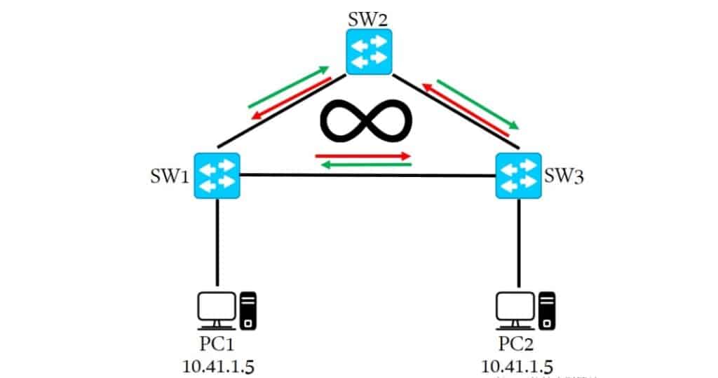
The Spanning Tree Protocol (STP) prevents loops and provides redundancy in Layer 2 networks. In a LAN with multiple redundant paths, loops may cause broadcast storms and MAC address learning errors. STP builds a spanning tree and disables certain links in loops to eliminate them.
How STP Works
- Each device (switch) has a Bridge Priority and a Bridge ID (BID).
- Devices exchange BPDUs (Bridge Protocol Data Units) to share information.
- Each switch evaluates received BPDUs to determine the Root Bridge and the shortest path.
- Devices select their Root Port or non-root ports based on the topology.
STP is suitable for smaller-scale networks but has slow convergence and limited responsiveness to topology changes.
Functions of STP
- Loop Prevention: STP prevents loops by calculating a spanning tree and blocking redundant links.
- Redundancy: If a link fails, STP recalculates the spanning tree and enables backup links.
- Root Election: STP elects a Root Bridge as the tree’s root to define the topology.
Applications of STP
- Preventing Broadcast Storms: Stops broadcast frames from endlessly circulating.
- Providing Redundancy: Dynamically adjusts the tree to maintain connectivity during link failures.
- Interconnecting Multi-layer Switches: Builds spanning trees across interconnected switches.
What is RSTP
To improve STP’s convergence speed and performance, RSTP (Rapid Spanning Tree Protocol) was introduced. RSTP is an enhancement of STP, retaining its basic principles but adding mechanisms to accelerate convergence.
RSTP improves on STP’s slow convergence by introducing new port roles, simplified states, and fast convergence algorithms, achieving near-instant spanning tree recalculation.
Key Improvements in RSTP
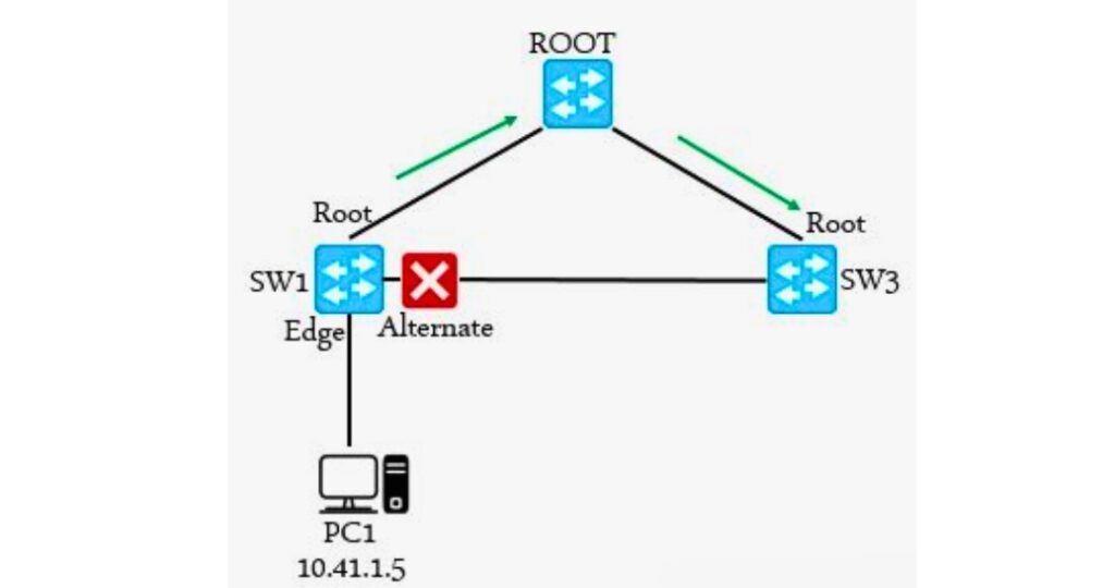
- Port States: RSTP reduces states to three—Designated, Root, and Alternate—compared with STP’s multiple states. This simplifies transitions and speeds convergence.
- Fast Convergence: By reducing BPDU intervals and timers, RSTP recalculates the spanning tree more quickly after topology changes.
- Continuous Monitoring: RSTP sends BPDUs periodically to monitor link status. If no BPDU is received within a defined interval, it assumes link failure and quickly recalculates.
RSTP provides faster convergence and better performance than STP. It is well-suited for medium-scale networks where responsiveness to change is crucial.
Functions of RSTP
- Rapid Convergence: Quickly recalculates the spanning tree during link or topology failures.
- Backward Compatibility: RSTP interoperates with STP and can function in mixed environments.
Applications of RSTP
- Improving Convergence Speed: Reduces downtime caused by topology changes.
- Redundancy and Loop Protection: Like STP, it prevents loops and ensures redundant paths.
What is MSTP ?
In large networks with multiple VLANs, STP and RSTP can only build a single spanning tree across the network. To solve this, MSTP (Multiple Spanning Tree Protocol) was developed. MSTP allows multiple independent spanning trees to be created in the same network, enabling better flexibility and scalability.
MSTP allows multiple spanning tree instances (MSTIs), each responsible for different VLANs. This provides better load balancing and resource utilization.
Key Features of MSTP
- Instances: MSTP divides the network into multiple spanning tree instances, each corresponding to one or more VLANs.
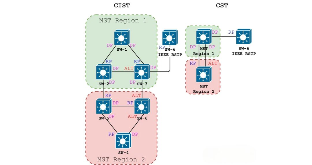
- Regions: The network is divided into MST regions, each with its own Root Bridge and tree. This reduces computation complexity and improves scalability.
- VLAN-to-Instance Mapping: VLANs are mapped to spanning tree instances, giving each VLAN its own tree.
MSTP adapts well to large-scale networks, offering flexibility and scalability to meet different VLAN and region requirements.
Functions of MSTP
- Multiple Spanning Trees: Allows multiple instances within one network.
- Load Balancing: Distributes VLANs across different trees for optimal link utilization.
- Backward Compatibility: Works seamlessly with RSTP and STP in mixed networks.
For a deep dive into regions, CIST/IST/MSTI, and VLAN mapping, see MSTP protocol
Comparison of STP, RSTP, and MSTP
Functional Comparison
|
Feature |
STP |
RSTP |
MSTP |
|---|---|---|---|
|
Loop Elimination |
Yes |
Yes |
Yes |
|
Rapid Convergence |
No |
Yes |
Yes |
|
Multi-VLAN Support |
No |
No |
Yes |
|
Topology Scalability |
Small networks |
Medium networks |
Large networks with multi-VLAN |
Performance Comparison
|
Metric |
STP |
RSTP |
MSTP |
|---|---|---|---|
|
Convergence Speed |
Slow |
Fast |
Fast |
|
State Transitions |
Frequent |
Fewer |
Moderate |
|
Configuration |
Low complexity |
Low complexity |
Higher complexity |
|
Scalability |
Small networks |
Medium and small VLAN networks |
Large multi-VLAN networks |
|
Network Size |
Small |
Medium |
Large |
Use Case Comparison
|
Scenario |
STP |
RSTP |
MSTP |
|---|---|---|---|
|
Small Networks |
Yes |
Yes |
Yes |
|
Medium-Sized Networks |
No |
Yes |
Yes |
|
Large Multi-VLAN Environments |
No |
No |
Yes |
|
Fast Convergence Required |
No |
Yes |
Yes |
|
Flexible Multi-Tree Configuration |
No |
No |
Yes |
BPDU in Spanning Tree Protocols (STP vs RSTP vs MSTP)
In spanning-tree protocols, topology computation between devices is performed by exchanging BPDUs (Bridge Protocol Data Units). These BPDU messages carry all the information required to compute and maintain a loop-free spanning-tree topology.
BPDU Types
Configuration BPDU (STP)
- Description: Used by STP to compute and maintain the spanning tree.
- Purpose: Determines the Root Bridge, Root Port, Designated Port, and other key parameters.
- Protocol Version Identifier:
0 - BPDU Type:
0x00 - Core Fields:
- Root Identifier: The BID of the current Root Bridge (Bridge Priority + Bridge MAC).
- Root Path Cost: Cumulative path cost from a port to the Root Bridge across all intermediate bridges and ports.
- Bridge Identifier: The BID of the sending device.
- Port Identifier: The PID of the sending port (Port Priority + Port Number).
RST BPDU (RSTP)
- Description: Used by RSTP to compute and maintain the spanning tree with rapid convergence.
- Purpose: Enables fast reconvergence of the spanning-tree topology.
- Protocol Version Identifier:
2 - BPDU Type:
0x02 - Notes: Structurally similar to Configuration BPDU, with an additional Version 1 Length field and use of the middle six bits in the Flags field.
MST BPDU (MSTP)
- Description: Used by MSTP to compute and maintain multiple spanning-tree instances.
- Purpose: Each MST instance uses MST BPDUs for its own topology calculation.
- Protocol Version Identifier:
3 - BPDU Type:
0x02 - Notes: The first 36 bytes are identical to RST BPDU. From byte 37 onward, MSTP-specific fields appear. The trailing MSTI configuration information consists of one or more concatenated MSTI info groups.
TCN BPDU (Topology Change Notification)
- Description: Notifies the network that a topology change has occurred.
- Purpose: Triggers relevant devices to recompute the topology after a change.
- Protocol Version Identifier:
0 - BPDU Type:
0x80 - Length: 4 bytes, using the Protocol Identifier, Protocol Version Identifier, and BPDU Type fields.
BPDU Frame Format
BPDUs are encapsulated in Ethernet frames with the destination MAC address typically set to 01-80-C2-00-00-00.
A BPDU contains many fields; two key fields identify version and type:
- Protocol Version Identifier (PVID): Specifies the spanning-tree protocol version.
- BPDU Type: Specifies the BPDU kind, such as Configuration BPDU, RST BPDU, MST BPDU, or TCN BPDU.
These values allow devices to recognize BPDU types and execute the appropriate topology computations. By continuously exchanging BPDUs, spanning-tree protocols maintain awareness of topology changes and adjust according to the algorithm to preserve loop protection and network stability.
Spanning Tree Timers
Hello Time and Timeout
- Devices send BPDUs to neighbors at each Hello Time interval to verify link health.
- Timeout formula:
Timeout = Hello Time × 3 × Timer Factor - Timer Factor is a configurable parameter used to tune the timeout.
Forward Delay
- Forward Delay defines the delay for state transitions.
- After a link failure triggers a recalculation, newly selected Root Ports and Designated Ports must wait 2 × Forward Delay before entering Forwarding state.
- Default Forward Delay: 15 seconds.
Max Age and Message Age
- Max Age is the BPDU aging timer (configurable on the Root Bridge).
- Message Age is the total elapsed time from when a BPDU left the Root to when the current device received it.
- Upon receiving a BPDU, a non-root bridge compares Message Age with Max Age:
- If Message Age ≤ Max Age, the BPDU remains valid and can be forwarded.
- If Message Age > Max Age, the BPDU is considered aged out and is discarded.
- Message Age increases by 1 for each bridge hop the BPDU traverses.
These timers and timeout mechanisms help spanning-tree protocols react quickly yet stably to topology changes, ensuring timely adjustments to the tree and effective loop prevention.
When to use STP vs RSTP vs MSTP?
STP Use Cases (Legacy and Low-Criticality Environments)
Although STP is slower in convergence, it is still used in some networks due to its simplicity and legacy support:
- Campus LANs with Old Hardware: Older switches that only support STP, often in small office or school environments.
- Simple Backup Links: Environments where downtime of 30–50 seconds is acceptable, such as non-critical administrative networks.
- Lab and Training Environments: For educational purposes, STP remains a standard way to demonstrate loop prevention.
RSTP Use Cases (Modern Enterprise and Industrial Networks)
RSTP provides rapid convergence, making it the preferred choice in most modern environments:
- Enterprise Campus Networks: Core and distribution switches rely on RSTP to quickly recover from link or switch failures, minimizing user disruption.
- Data Centers: With server clusters and storage systems, RSTP ensures sub-second failover, which is essential for high availability and cloud services.
- Industrial Automation: In manufacturing plants or energy facilities, downtime even for a few seconds can disrupt real-time communication between PLCs and sensors. RSTP supports fast recovery in such mission-critical applications.
- Wireless Backhaul and Metro Ethernet: Some service providers use RSTP to protect ring topologies, ensuring rapid failover in city-wide access networks.
MSTP Use Cases (Scalable VLAN-Based Deployments)
MSTP extends RSTP with the ability to run multiple spanning tree instances, providing scalability and load balancing:
- Large Campus Networks with VLAN Segmentation: Universities or hospitals often run hundreds of VLANs. MSTP allows mapping different VLAN groups to different spanning trees for traffic distribution.
- Service Provider Networks: ISPs often deploy MSTP in metro Ethernet rings to segregate customer VLANs and achieve load balancing across redundant paths.
- Data Center VLAN Optimization: In multi-tenant data centers, MSTP enables efficient traffic distribution across VLANs, avoiding bottlenecks on a single spanning tree path.
- Enterprise Multi-Building Campuses: MSTP is ideal for scenarios where multiple buildings are interconnected with VLAN-based traffic engineering requirements.
FAQ
-
What is the main difference between STP and RSTP?
The main difference is convergence speed. STP (Spanning Tree Protocol) typically requires 30–50 seconds to stabilize after a topology change, while RSTP (Rapid Spanning Tree Protocol) can achieve convergence in less than 1 second.
-
Is RSTP backward compatible with STP?
Yes. RSTP is fully backward compatible with STP. When an RSTP-enabled switch connects to an STP-only device, it automatically falls back to STP mode to maintain compatibility.
-
When should I use STP instead of RSTP?
STP should be used in legacy networks or with older hardware that does not support RSTP. It may also be suitable for small networks where downtime is acceptable and rapid failover is not required.
-
What are the advantages of RSTP over STP?
RSTP provides rapid convergence, uses Alternate and Backup ports for redundancy, and supports Edge Ports that immediately forward traffic to hosts. This makes it more efficient and reliable for modern enterprise and data center networks.
-
How does MSTP relate to STP and RSTP?
MSTP (Multiple Spanning Tree Protocol) builds on RSTP and allows multiple spanning tree instances. This enables VLAN-based load balancing and scalability, making MSTP ideal for large enterprise and service provider networks.
Conclusion
The debate of STP vs RSTP is a balance between legacy stability and modern efficiency.
- STP: Stable but outdated, with long convergence delays.
- RSTP: Fast, efficient, backward compatible — ideal for modern enterprises.
- MSTP: Extends RSTP with VLAN-based multiple spanning trees for load balancing and scalability.
By understanding these protocols, network engineers can build resilient, loop-free, and scalable Layer 2 networks tailored to their business needs.
For practical setup examples, follow our Spanning Tree Configuration Guide