Cisco Switch Ports Explained: Physical Types, Logical Modes, and CLI Configuration
Cisco switch ports are categorized by their physical hardware interfaces (such as RJ45 copper, fiber-optic SFP uplinks, and console ports), their bandwidth speed capacities (Gigabit, 10G, 100G), and their logical operating modes. A switchport can be configured logically as an access port for a single VLAN, a trunk port utilizing 802.1Q encapsulation to carry multiple VLANs, or a routed port for Layer 3 IP forwarding.
Understanding Cisco Switch Ports: Physical vs. Logical Interfaces
When architecting an enterprise campus or data center network, network engineers must differentiate between the physical characteristics of a switch port (the actual hardware transceiver, medium, and speed) and its logical state (how the Cisco IOS operating system processes the frames passing through that hardware).
Common Switch Port Types
The physical medium of a switch port dictates how it connects to the broader network, its maximum transmission distance, and its electrical capabilities.
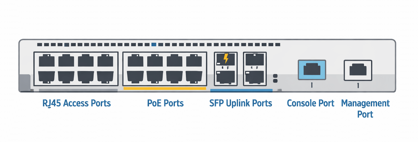
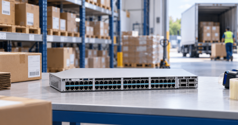
- RJ45 Copper Ports: The most ubiquitous port type, utilizing standard twisted-pair Ethernet cables (Cat5e, Cat6, Cat6a). These are typically used for downstream access connections to desktop PCs, Wi-Fi access points, and IP phones.
- Fiber Optic Transceiver Ports (SFP/SFP+/QSFP): Located typically on the far right of the switch faceplate or on modular expansion cards. Instead of fixed ports, these are empty slots that accept hot-swappable transceivers, allowing engineers to choose between short-range (SR) multimode fiber or long-range (LR) single-mode fiber based on the distance to the next switch.
- Power over Ethernet (PoE) Ports: Physically identical to standard RJ45 copper ports, but engineered to deliver direct current (DC) electrical power alongside data. They support IEEE standards such as PoE+ (30W) and UPOE/802.3bt (up to 90W) for powering PTZ cameras and smart lighting.
- Console and Management Ports: Dedicated out-of-band management ports. They do not switch network traffic. Instead, they provide direct serial access (via RJ45 or USB mini-B) to the Cisco Command Line Interface (CLI) for disaster recovery when the network is down.
Switch Port Speed Types
Understanding port speed is critical not only for bandwidth capacity planning but also for navigating the Cisco CLI, as the interface speed dictates the port’s naming convention in the operating system.
- Fast Ethernet (Fa): Provides speeds up to 100 Mbps. While largely obsolete for modern data transit, Fast Ethernet ports are still found on legacy switches and out-of-band management interfaces. In the CLI, they are designated as
FastEthernet0/1orFa0/1. - Gigabit Ethernet (Gi): Provides speeds of 1 Gbps (1,000 Mbps). This is the current standard baseline for enterprise access layer ports connecting to end-user devices. In the CLI, they are designated as
GigabitEthernet1/0/1orGi1/0/1. - Multigigabit (mGig): A newer standard (IEEE 802.3bz) utilized heavily on modern Catalyst 9300 switches. It allows RJ45 copper ports to negotiate intermediate speeds of 2.5 Gbps or 5 Gbps over existing Cat5e/Cat6 cabling, specifically designed to support high-throughput Wi-Fi 6 and Wi-Fi 7 access points.
- 10 Gigabit Ethernet (Te): Provides speeds of 10 Gbps. Typically utilized via SFP+ fiber transceivers for uplinks between the access and distribution layers, or for direct connections to enterprise servers. In the CLI, they are designated as
TenGigabitEthernet1/1/1orTe1/1/1. - 40G, 100G, and 400G Ethernet: Reserved for ultra-high-throughput aggregation and core layers, utilizing QSFP+, QSFP28, and QSFP-DD form factors. These ports form the backbone of modern enterprise campuses and data centers. In the CLI, a 100G port is typically designated as
HundredGigE1/0/1.
Logical Switchport Modes
Regardless of whether a port is a copper Gigabit interface or a fiber 10G interface, its behavior is dictated by its logical configuration in the Cisco IOS software.
- What is an Access Port? An access port belongs to and carries the traffic of only one specific Virtual Local Area Network (VLAN). It transmits untagged Ethernet frames. Devices plugged into an access port are completely unaware that VLANs exist on the network.
- What is a Trunk Port? A trunk port is configured to carry traffic for multiple VLANs simultaneously across a single physical link. To keep the traffic separated, the switch injects an IEEE 802.1Q tag into the Ethernet header, which identifies the VLAN ID before sending it across the wire to another switch or firewall.
- Routed Ports and Layer 3 Interfaces: On a multi-layer switch (like the Catalyst 9300 or 9500), a physical port can be stripped of its Layer 2 switching capabilities entirely. By configuring it as a routed port (using the
no switchportcommand), it functions exactly like an interface on a dedicated hardware router.
Access Port vs Trunk Port vs Routed Port Comparison
To make immediate architectural and configuration decisions, network engineers rely on strict operational boundaries between port types.
Access Port vs. Trunk Port: Key Differences
| Feature / Metric | Access Port | Trunk Port |
| Primary Use Case | Connecting end-user devices (PCs, printers, IP cameras). | Connecting network infrastructure (Switch-to-Switch, Switch-to-Router). |
| VLAN Capacity | One single data VLAN (plus one optional Voice VLAN). | Multiple VLANs (up to 4,094 theoretically). |
| Frame Encapsulation | Sends and receives standard, untagged 802.3 Ethernet frames. | Uses IEEE 802.1Q to insert a 4-byte VLAN tag into the frame header. |
| Native VLAN Behavior | Not applicable; all traffic is strictly native to the assigned VLAN. | Untagged traffic falling onto a trunk link is assigned to the “Native VLAN” (default is VLAN 1). |
| Security Risk | Vulnerable to MAC flooding; requires Port Security. | Vulnerable to VLAN Hopping attacks; requires Native VLAN pruning and DTP disabling. |
Layer 2 Switching vs. Layer 3 Routing Ports
| Operational Layer | Layer 2 Switchport (Access/Trunk) | Layer 3 Routed Port |
| Forwarding Logic | Forwards based on destination MAC addresses via the CAM table. | Routes based on destination IP addresses via the Routing Table (FIB). |
| Broadcast Handling | Forwards broadcast frames to all ports in the same VLAN. | Strictly drops broadcast frames; acts as a broadcast domain boundary. |
| Configuration Command | switchport mode access | no switchport followed by ip address x.x.x.x |
How to Configure a Cisco Switch Port (CLI Guide)
Translating architectural theory into operational reality requires precise Cisco IOS command-line execution. The following configurations represent enterprise best practices.
1. Initial Access via the Cisco Switch Console Port
To configure a factory-default switch, connect a rollover cable from your laptop to the switch’s console port. Use a terminal emulator (like PuTTY or TeraTerm) with the following standard serial settings:
- Baud Rate: 9600
- Data Bits: 8
- Parity: None
- Stop Bits: 1
- Flow Control: None
2. How to Configure an Access Port and Assign VLANs
This configures a standard gigabit port for a desktop computer, placing it securely into VLAN 10.
Plaintext
Switch> enable
Switch# configure terminal
Switch(config)# interface GigabitEthernet1/0/1
Switch(config-if)# description USER_DESKTOP
Switch(config-if)# switchport mode access
Switch(config-if)# switchport access vlan 10
Switch(config-if)# spanning-tree portfast
Switch(config-if)# no shutdown
(Note: spanning-tree portfast immediately transitions the port to a forwarding state, preventing DHCP timeouts for end devices.)
3. How to Configure a Trunk Port and Native VLANs
This configures a 10G uplink port to another switch, allowing only specific VLANs and modifying the native VLAN for security against VLAN hopping.
Plaintext
Switch(config)# interface TenGigabitEthernet1/1/1
Switch(config-if)# description UPLINK_TO_CORE
Switch(config-if)# switchport trunk encapsulation dot1q
Switch(config-if)# switchport mode trunk
Switch(config-if)# switchport trunk native vlan 99
Switch(config-if)# switchport trunk allowed vlan 10,20,30,99
Switch(config-if)# switchport nonegotiate
(Note: switchport nonegotiate completely disables Dynamic Trunking Protocol (DTP), a mandatory security best practice.)
4. Implementing Port Security and BPDU Guard
To prevent unauthorized devices or rogue switches from causing network loops or MAC address table exhaustion on access ports:
Plaintext
Switch(config)# interface GigabitEthernet1/0/1
Switch(config-if)# switchport port-security
Switch(config-if)# switchport port-security maximum 2
Switch(config-if)# switchport port-security violation restrict
Switch(config-if)# switchport port-security mac-address sticky
Switch(config-if)# spanning-tree bpduguard enable
Mapping Switch Ports to Enterprise Network Architecture
Understanding how to configure a port is tactical; knowing where to deploy specific port types is strategic.
The Traditional Three-Tier Hierarchical Model
In a standard campus network, ports are mapped to specific roles:
- The Access Layer: 100% of downlink ports are configured as Access Ports facing end-users. The uplinks to the distribution block are configured as Trunk Ports carrying multiple VLANs.
- The Distribution Layer: Downlinks facing the access switches are Trunk Ports. Uplinks facing the core are increasingly configured as Routed Ports (Layer 3) to isolate spanning-tree domains and utilize Equal-Cost Multi-Path (ECMP) routing.
- The Core Layer: Every single interface is configured as a Routed Port. The core does not switch Layer 2 VLANs; it strictly routes IP packets at ultra-high speeds.
The Modern Leaf-Spine Architecture for Data Centers
Traditional three-tier networks rely heavily on trunk ports and Spanning Tree Protocol (STP), which blocks redundant links. Modern data centers experience massive “East-West” traffic (server-to-server communication).
To solve STP bottlenecks, data centers utilize a Leaf-Spine architecture. In this design, every single uplink port between a Leaf switch and a Spine switch is configured as a Layer 3 Routed Port. There are no trunk ports between switches. Layer 2 VLANs are instead encapsulated inside Layer 3 UDP packets using VXLAN (Virtual Extensible LAN) with BGP EVPN. This allows all links to remain active, providing massive bandwidth scaling and sub-millisecond deterministic latency.
Hardware Considerations for Enterprise Procurement
Procurement and capacity planning heavily revolve around the physical capabilities of the switch ports.
Calculating PoE Budgets and Cable Loss
When deploying a 48-port PoE switch for an IP surveillance network, assigning every port to a camera is restricted by the power supply. If a Catalyst switch has a 715W power supply, and the switch hardware consumes 150W, you only have a 565W PoE Budget. If you connect 48 PTZ cameras drawing 30W each (1,440W total), the switch will aggressively shut down ports. Engineers must calculate total endpoint wattage and account for resistance/voltage drop over Category 6 copper cable runs exceeding 80 meters.
Selecting Uplink Capacity to Prevent Oversubscription
If you have a 48-port switch where every employee is connected at 1 Gigabit (48 Gbps of potential downstream bandwidth), and your uplink to the core is a single 10G SFP+ trunk port, your oversubscription ratio is 4.8:1. For standard office traffic, a 20:1 ratio is often acceptable. However, for a data center storage switch, engineers must provision 40G or 100G QSFP28 uplink ports to ensure a non-blocking, 1:1 architecture where uplink bandwidth equals total downstream capacity.
Diagnosing and Troubleshooting Common Cisco Port Errors
When the network fails, engineers isolate the issue by examining port states and statistics.
Resolving Native VLAN Mismatches on Trunk Links
If two connected switches have different Native VLANs configured on their trunk ports (e.g., Switch A is Native VLAN 1, Switch B is Native VLAN 99), Cisco CDP will generate continuous Syslog error messages:
%CDP-4-NATIVE_VLAN_MISMATCH: Native VLAN mismatch discovered...
This breaks Spanning Tree and leaks traffic between VLANs. Engineers must ensure the switchport trunk native vlan X command matches perfectly on both sides of the optical fiber.
Recovering Interfaces from ‘Err-Disable’ States
If a port detects a security violation (such as receiving a BPDU packet on an access port configured with BPDU Guard, or exceeding its maximum allowed MAC addresses via Port Security), the Cisco operating system will place the port into an err-disable state, physically shutting off traffic.
- Run
show interfaces status err-disabledto identify the specific port and the root cause (e.g.,bpduguardorpsecure-violation). - Fix the physical issue (e.g., unplug the rogue unmanaged switch the employee brought from home).
- To recover the port, enter interface configuration mode and bounce the port by typing
shutdown, followed byno shutdown.
Verifying Physical Layer Connections
Always start troubleshooting at Layer 1. Use the command show interfaces GigabitEthernet1/0/1 to check for physical errors. High CRC errors or input errors indicate a failing copper cable, electromagnetic interference, or dirty fiber optic transceiver heads.
Frequently Asked Questions About Cisco Switch Ports
What is the difference between an aggregation switch and a core switch?
An aggregation (or distribution) switch typically acts as the boundary between Layer 2 and Layer 3, terminating VLANs via trunk ports and enforcing Access Control List (ACL) security policies. A core switch sits above aggregation, operating purely with high-speed routed ports to transit data across the campus backbone with absolute minimum latency, devoid of complex ACL processing.
Can an access switch port carry multiple VLANs simultaneously?
By definition, a standard access port carries only one data VLAN. However, Cisco provides a specific exception for VoIP environments: an access port can be configured with a “Voice VLAN” parameter. This allows the port to carry one untagged data VLAN for the desktop PC and one 802.1Q tagged Voice VLAN for the Cisco IP phone connected to the same physical cable.
How do I configure a dedicated voice VLAN for a Cisco IP Phone?
You apply the voice VLAN command on top of the standard access port configuration:Switch(config-if)# switchport mode accessSwitch(config-if)# switchport access vlan 10Switch(config-if)# switchport voice vlan 50
When should network engineers use a crossover cable versus a straight-through cable?
Historically, connecting two switches together via their copper RJ45 ports required a crossover cable because the transmit (Tx) and receive (Rx) pins aligned. Connecting a PC to a switch required a straight-through cable. However, virtually all modern Cisco switches support Auto-MDIX (Automatic Medium-Dependent Interface Crossover), which automatically detects the pinout and corrects the electrical signaling in hardware, rendering crossover cables obsolete.