Core vs Distribution vs Access Switches: The Complete Architecture Guide
In enterprise networking, the hierarchical three-tier model is divided into three distinct roles: access switches (which connect end-user devices to the network via Layer 2), distribution switches (which route inter-VLAN traffic and enforce security policies at Layer 3), and core switches (which provide ultra-low latency, high-speed backbone transit across the entire campus).
Understanding the precise engineering boundaries between these three layers is the foundational principle of modern network architecture. Failing to properly categorize and deploy switches according to their designated tier leads to broadcast storms, routing loops, and severe physical bottlenecks that can cripple enterprise productivity.
This comprehensive engineering guide deconstructs the core, distribution, and access layers. It will analyze the required hardware specifications for each tier, detail the specific routing and switching protocols that must operate at each boundary, and map these theoretical frameworks to real-world deployment scenarios utilizing the Cisco Catalyst 9000 hardware ecosystem. Furthermore, we will explore how modern data center traffic patterns are forcing a migration toward alternative topologies like the Collapsed Core and the Spine-Leaf fabric.

Understanding the 3-Tier Enterprise Network Architecture
Before delving into the specific hardware, network architects must understand why the hierarchical model exists. In the early days of local area networking, organizations utilized “flat” network designs. In a flat network, every endpoint (workstations, servers, printers) resides in a single, massive broadcast domain, often connected by simple hubs or basic unmanaged Layer 2 switches.
While a flat network is cheap to build, it is architecturally disastrous at scale. When a device sends an Address Resolution Protocol (ARP) request, that broadcast frame is flooded out of every single port on the network. In a network with thousands of devices, the sheer volume of background broadcast traffic consumes all available bandwidth, leaving no room for actual data transmission. Furthermore, a single spanning-tree loop or a faulty network interface card (NIC) can bring down the entire corporate infrastructure because there are no logical boundaries to contain the failure.
To solve this scaling crisis, Cisco introduced the Hierarchical Internetworking Model, commonly referred to as the 3-Tier Architecture.
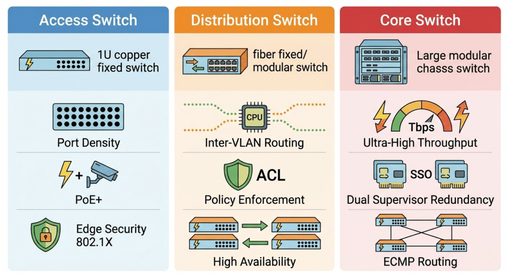
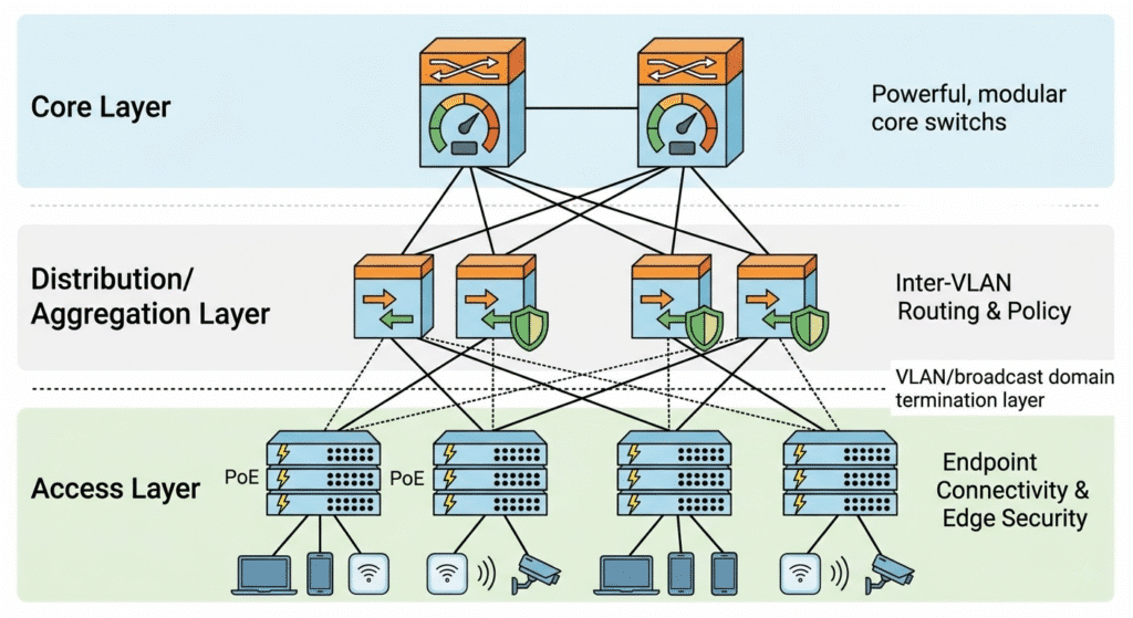
This architectural framework divides the network into three distinct layers, each engineered with a highly specific, modular purpose:
- The Access Layer: Grants end devices entry into the network.
- The Distribution Layer: Aggregates access switches, routes traffic between virtual networks, and enforces security boundaries.
- The Core Layer: Functions as the high-speed highway connecting different buildings and data centers together.
The genius of the 3-tier model is modularity. By compartmentalizing the network, architects can isolate hardware failures to a single building or floor, scale port density without redesigning the entire routing table, and apply consistent security policies at centralized choke points.
Access Layer Switches: The Network Edge
The access layer is the entry point into the enterprise network. It is the only tier that physically interacts with non-infrastructure devices, making it the most vulnerable and hardware-intensive segment of the campus architecture.
What is an Access Switch?
An access switch (often referred to as an edge switch) is a hardware device deployed in local wiring closets designed to connect end-user endpoints—such as desktop computers, Voice over IP (VoIP) phones, Wi-Fi access points, and IP surveillance cameras—to the broader corporate network.
Key Features and Requirements of Access Switches
Because they sit at the edge of the network, access switches are not evaluated on their ability to process massive routing tables. Instead, they are evaluated on port density, power delivery, and port-level security.
- Port Density and Cost per Port: The access layer accounts for the vast majority of physical switch purchases in an enterprise. A single floor of an office building may require hundreds of ports. Therefore, access switches are typically fixed-configuration devices (24 or 48 ports) that prioritize a low cost-per-port metric. To scale density within a single wiring closet, modern access switches utilize stacking technologies (like Cisco StackWise) to bind multiple physical switches into one logical management plane.
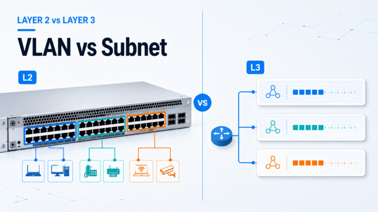
- Layer 2 Switching and VLAN Tagging: The primary function of the access layer is data link layer (OSI Layer 2) switching. Access switches read the destination MAC address of incoming frames and forward them to the correct local port. More importantly, they assign endpoints to specific Virtual Local Area Networks (VLANs). When an employee’s PC sends data, the access switch injects an IEEE 802.1Q VLAN tag into the frame, segregating that traffic from the guest Wi-Fi or IoT devices connected to the same physical switch.
- Power over Ethernet (PoE): Modern access switches act as the electrical grid for the IT environment. They must support advanced Power over Ethernet standards to power endpoint devices directly over copper Category 6 cables. This includes standard PoE (802.3af, 15W), PoE+ (802.3at, 30W) for standard IP phones and Wi-Fi 5 APs, and UPOE/802.3bt (up to 90W) for high-draw devices like Pan-Tilt-Zoom (PTZ) security cameras and LED lighting systems.
- Spanning Tree Protocol (STP) Edge Features: Because employees can easily plug a cable into two wall jacks and create a catastrophic network loop, access switches must aggressively run loop-prevention protocols. Features like PortFast (allowing endpoints to bypass STP listening states) and BPDU Guard (immediately shutting down an access port if another switch is detected) are mandatory at this layer.
- Network Access Control (NAC): The access switch is the network’s bouncer. It must support 802.1X authentication, demanding that any plugged-in device presents a valid digital certificate or credentials to a RADIUS server (like Cisco Identity Services Engine) before the switch port will transition to a forwarding state. Additional edge security features like DHCP Snooping and Dynamic ARP Inspection (DAI) are executed entirely at the access layer.
Distribution Layer Switches: The Policy Enforcer
Moving up the hierarchy, the wiring closets on every floor must connect back to a centralized point. This is the realm of the distribution layer, frequently referred to interchangeably as the distribution layer.
What is an Distribution Switch?
A distribution switch acts as the strategic intermediary between the localized access layer and the high-speed core. Its primary purpose is to aggregate the uplink connections from dozens of access switches, route traffic between different VLANs, and serve as the absolute boundary between Layer 2 switching domains and Layer 3 routing domains.
Containing the Failure Domain (The Layer 2 / Layer 3 Boundary)
The most critical architectural concept in the 3-tier model is the restriction of the broadcast domain. A broadcast domain must never extend beyond the distribution layer.
In a properly designed campus network, the access switches operate purely at Layer 2. The distribution switches operate at Layer 3 (the Network Layer). The distribution switch hosts the Switched Virtual Interfaces (SVIs) that act as the default gateway for the access layer VLANs.
When a PC on VLAN 10 (Finance) wants to talk to a printer on VLAN 20 (Operations), the traffic travels up to the distribution switch. The distribution switch strips the Layer 2 frame, examines the Layer 3 IP address, consults its internal routing table, and routes the packet down to the correct VLAN.
By terminating the VLANs at the distribution layer, network architects ensure that a Layer 2 broadcast storm originating in the Finance department physically cannot propagate through the distribution switch into the rest of the campus. The distribution switch effectively isolates hardware failures, rogue DHCP servers, and spanning-tree loops to a single building or floor.
Key Features and Requirements of Distribution Switches
Because they perform the heavy lifting of traffic analysis and routing, distribution switches require significantly more computational horsepower (CPU and RAM) than access switches.
- Layer 3 Routing Protocols: Distribution switches must maintain dynamic routing tables. They actively run interior gateway protocols (IGPs) such as Open Shortest Path First (OSPF) or Enhanced Interior Gateway Routing Protocol (EIGRP). They receive routes from the core layer and advertise summarized routes from the access layer, significantly reducing the routing overhead on the network backbone.
- First Hop Redundancy Protocols (FHRP): To ensure high availability, distribution switches are deployed in redundant pairs. They utilize protocols like Hot Standby Router Protocol (HSRP) or Virtual Router Redundancy Protocol (VRRP) to share a single virtual IP address. If the primary distribution switch suffers a catastrophic hardware failure, the secondary switch assumes the gateway IP address in milliseconds, ensuring the access layer experiences zero downtime.
- Access Control Lists (ACLs) and Security Policies: The distribution layer is the policy enforcement point of the enterprise. If the IT department dictates that the Guest Wi-Fi subnet cannot communicate with the internal active directory servers, that rule is written as an Access Control List (ACL) and applied to the distribution switch’s CPU. The distribution switch acts as an internal firewall, meticulously dropping unauthorized packets before they can reach the core.
- Quality of Service (QoS) Trust Boundaries: When voice and video traffic enters the distribution layer, the switch must examine the Differentiated Services Code Point (DSCP) markings on the packets. The distribution switch enforces the QoS policy, guaranteeing that latency-sensitive VoIP packets are placed in priority hardware queues before being transmitted across the core uplinks.
- High-Bandwidth distribution: Distribution switches must ingest massive amounts of data from the access layer. Therefore, their downlink ports are typically 10 Gigabit Ethernet (10GbE) or 25GbE fiber optics, while their uplinks to the core utilize 40GbE or 100GbE transceivers.
Core Layer Switches: The High-Speed Backbone
The pinnacle of the enterprise topology is the core layer. The core is the high-speed digital highway that connects the various distribution blocks (different buildings on a campus, or different regional data centers) to one another, as well as providing the primary egress path to the Wide Area Network (WAN) and the public internet.
What is a Core Switch?
A core switch is a massive, highly resilient, modular Layer 3 routing platform designed with one singular objective: to switch packets as fast as physically possible with absolute zero packet loss and microsecond latency.
The Golden Rule of the Core: Keep It Clean
Network architects adhere to a strict philosophy regarding the core layer: do not do anything to slow down the packet. While the distribution layer is burdened with CPU-intensive tasks like ACL processing, deep packet inspection, inter-VLAN routing, and QoS marking, the core layer must be kept entirely “clean” of these complex policies. Applying an ACL to a core switch forces the switch’s Application-Specific Integrated Circuits (ASICs) to pause and evaluate the packet against a rule set, introducing latency. The core must remain a pure, unhindered transit layer.
Key Features and Requirements of Core Switches
Core switches are the most expensive, highly engineered pieces of equipment in the enterprise portfolio. They operate exclusively at Layer 3 and prioritize raw backplane capacity over port density.
- Ultra-High Throughput: Core switches do not utilize standard 1 Gigabit copper ports. Their chassis are populated with high-density fiber optic line cards supporting 40G, 100G, and increasingly 400G ethernet (QSFP-DD). A modern core switch backplane must be capable of switching tens of Terabits per second (Tbps) without dropping frames.
- Absolute Hardware Redundancy: A failure at the access layer affects a few users. A failure at the distribution layer affects a building. A failure at the core layer takes the entire global enterprise offline. Therefore, core switches are invariably modular chassis systems. They feature multiple hot-swappable power supplies tied to distinct electrical grids. More importantly, they feature Dual Supervisor Engines. If the primary brain of the core switch crashes, the standby supervisor engine performs Stateful Switchover (SSO) and assumes control of the backplane without dropping a single active network session.
- Equal-Cost Multi-Path (ECMP) Routing: Core switches rely heavily on dynamic routing protocols (like OSPF or BGP). Because the core is a meshed topology of Layer 3 links, Spanning Tree Protocol (STP) is completely disabled. Instead, core switches use ECMP to actively balance traffic loads across multiple active links simultaneously, maximizing the utilization of the expensive fiber optic cables connecting the campus.
- In-Service Software Upgrades (ISSU): Core switches must never be powered down. When a critical security vulnerability requires a firmware update, core switches utilize ISSU. The chassis upgrades the standby supervisor, seamlessly fails over the traffic, and then upgrades the primary supervisor. This allows engineers to patch the core operating system with zero seconds of network downtime.
Core vs Distribution vs Access: Side-by-Side Comparison
To consolidate the engineering differences, the following matrix compares the precise capabilities and responsibilities of the three hardware tiers.
| Parameter | Access Layer | Distribution Layer | Core Layer |
| Primary Network Role | Endpoint connectivity & edge security | Policy enforcement, inter-VLAN routing, boundary control | High-speed backbone transit & campus interconnect |
| OSI Operating Layer | Primarily Layer 2 (Data Link) | Layer 3 (Network) | Strictly Layer 3 (Network) |
| Port Density & Types | High density (24/48 ports), mostly 1G/2.5G/5G Copper Base-T | Medium density, mostly 10G/25G SFP+ Fiber optic downlinks | Low port count, extremely high-speed 40G/100G/400G Fiber |
| Throughput Speed | Low to Medium (measured in Gbps) | High (measured in hundreds of Gbps) | Extreme (measured in Tbps) |
| Security & Policies | Port Security, 802.1X NAC, DHCP Snooping | Access Control Lists (ACLs), IPS/IDS integration | Minimal to None (Keep the core fast and clean) |
| High Availability | Stacking (StackWise), Redundant Uplinks | First Hop Redundancy (HSRP/VRRP), StackWise Virtual | Dual Supervisors, ISSU, ECMP Layer 3 Routing |
| Hardware Form Factor | 1RU Fixed Configuration, Stackable | 1RU Fixed or Modular Chassis | Massive Modular Chassis |
Traffic Flow Dynamics: North-South vs East-West
To understand why network architectures are evolving, one must analyze the physical direction in which data travels. Network engineers categorize traffic into two distinct vectors: North-South and East-West.
North-South Traffic
North-South traffic defines data moving vertically into and out of the network. When an employee on an access switch downloads a file from the public internet, or a remote user accesses an internal web server, the traffic travels “North” from the endpoint, through the access, distribution, and core layers, and out through the enterprise firewall. Historically, the 3-Tier architecture was explicitly designed to optimize this North-South flow. The bandwidth funnels from the high-density edge up to the high-speed core.
East-West Traffic
East-West traffic defines data moving horizontally within the data center or campus. When Server A backs up its database to Server B, or when a virtual machine (VM) migrates from one physical host to another via VMware vMotion, the data travels laterally.
With the rise of hyperconverged infrastructure, microservices architectures, and distributed AI computing clusters, modern enterprise traffic is now 80% East-West. The traditional 3-tier architecture struggles with this. If Server A is on one access switch and Server B is on another, their East-West traffic is forced to travel unnecessarily “North” up to the distribution layer, traverse the routing backplane, and travel “South” back down to the second switch. This routing “hairpin” introduces unacceptable latency (often called the “tromboning” effect) and saturates the uplinks.
Modern Network Design Alternatives: Spine-Leaf & Collapsed Core
Because traffic patterns have shifted and hardware capabilities have advanced, network architects frequently implement two major alternatives to the strict 3-tier model.
The Collapsed Core Architecture (2-Tier Design)
While massive university campuses and Fortune 500 headquarters require a dedicated core layer, a traditional 3-tier design is financially excessive and unnecessarily complex for a Small to Medium-sized Business (SMB) with fewer than 1,500 users.
Enter the Collapsed Core architecture. In a 2-tier collapsed core design, the responsibilities of the Distribution layer and the Core layer are merged into a single, high-performance hardware appliance. The access switches connect directly to these collapsed core switches.
The collapsed core switch performs inter-VLAN routing, enforces ACL security policies, and provides high-speed transit simultaneously. This drastically reduces Capital Expenditure (CapEx) by eliminating an entire tier of expensive fiber-optic hardware, while still maintaining a robust Layer 2 / Layer 3 boundary. Modern routing ASICs are now powerful enough to handle policy enforcement and high-speed transit on the same silicon without severe latency penalties.
Spine-Leaf Architecture vs Traditional 3-Tier
To solve the East-West traffic bottleneck in modern data centers, the industry has aggressively adopted the Spine-Leaf architecture (based on the Clos network topology).
In a Spine-Leaf fabric, the network is flattened into two tiers, but functions completely differently than a collapsed core:
- Leaf Switches: These replace the Access and Distribution layers. Servers and endpoints connect directly to the leaf switches. Every leaf switch acts as a Layer 3 boundary (implementing a technology like VXLAN BGP EVPN to stretch Layer 2 domains over a Layer 3 fabric).
- Spine Switches: These replace the Core layer. Crucially, every single Leaf switch connects to every single Spine switch in a full-mesh topology. The absolute advantage of the Spine-Leaf design is deterministic latency. No matter which two servers are communicating, their traffic is always exactly one hop away (Leaf -> Spine -> Leaf). If more East-West bandwidth is required, network engineers simply add another Spine switch to the fabric. This architecture is the undisputed standard for modern cloud data centers, AI compute clusters, and high-performance trading floors.
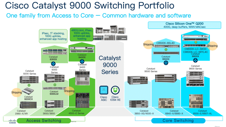
Real-World Hardware: Cisco Catalyst 9000 Series Mapping
Theoretical architecture is meaningless without understanding how it maps to actual commercial hardware. The Cisco Catalyst 9000 series is the industry standard for enterprise campus switching. When procurement officers build a Bill of Materials (BoM), the hardware choices perfectly mirror the architectural tiers.
Access Layer: Cisco Catalyst 9200 and 9300 Series
For the wiring closet, Cisco positions the Catalyst 9200 for basic branch deployments and the Catalyst 9300 for high-density enterprise access.
- Hardware Form Factor: 1 Rack Unit (1RU) fixed-configuration switches.
- Key Specs: Available in 24 or 48-port copper configurations. The Catalyst 9300 supports Multigigabit (mGig) ports (providing 2.5Gbps, 5Gbps, or 10Gbps over standard copper) to support modern Wi-Fi 6E/7 access points.
- HA Mechanism: They utilize StackWise-480 or StackWise-1T copper cables on the back panel to bind up to eight physical switches into a single logical access block, along with StackPower to share electrical loads across the stack.
Distribution Layer: Cisco Catalyst 9400 and 9500 Series
For the distribution block, organizations choose between modular expansion or high-density fixed routing.
- Catalyst 9400: A large, modular chassis designed for the wiring closet. If a building requires 300 copper access ports but demands absolute dual-supervisor redundancy (which StackWise cannot provide), the 9400 serves as a hybrid Access/Distribution switch.
- Catalyst 9500: A 1RU fixed-configuration switch populated entirely with 10G/25G or 40G/100G fiber optic ports. It is the premier choice for aggregating hundreds of Catalyst 9300 access switches or acting as the brains of a Collapsed Core architecture. It utilizes StackWise Virtual (SVL), allowing two separate 9500s to act as a single logical router over long-distance fiber cables.
Core Layer: Cisco Catalyst 9600 Series
For the absolute campus backbone, Cisco provides the Catalyst 9600.
- Hardware Form Factor: A massive, modular chassis designed for the data center or main distribution frame (MDF).
- Key Specs: It abandons copper entirely. When populated with high-end line cards, a single Catalyst 9600 chassis can provide up to 25.6 Terabits per second (Tbps) of switching capacity. It supports MACsec encryption at wire rate on 100G links and features physically distinct, redundant supervisor engines to execute zero-downtime ISSU firmware upgrades. It serves as the undisputed transit core for global enterprise networks.
Frequently Asked Questions (FAQ)
Can an access switch be used as a core switch?
In an enterprise environment, absolutely not. Access switches (like the Catalyst 9200) lack the CPU power to maintain massive BGP routing tables, lack the ASICs required to switch traffic at terabit speeds, and lack dual-supervisor hardware redundancy. Attempting to use a fixed access switch as a campus core will result in severe traffic bottlenecks, buffer overruns, and catastrophic single points of failure.
Should inter-VLAN routing happen at the core or distribution layer?
Inter-VLAN routing should always happen at the distribution layer. The distribution layer is designed to terminate Layer 2 broadcast domains and enforce routing policies. If you push inter-VLAN routing up to the core layer, you are polluting the high-speed backbone with unnecessary ARP broadcasts and CPU-intensive ACL evaluations, violating the core principle of keeping the backbone clean and fast.
Do core switches need to run spanning tree protocol (STP)?
No. In a properly designed hierarchical network, the core layer operates entirely at Layer 3 (IP routing). Because all links between the core and distribution switches are routed Layer 3 transit links, Layer 2 loops are physically impossible. Therefore, STP is irrelevant in the core. The core relies on routing protocols like OSPF and Equal-Cost Multi-Path (ECMP) to provide redundancy and load balancing.
When should a business upgrade from a Collapsed Core to a full 3-Tier architecture?
The transition is dictated by scale and physical geography. A collapsed core (2-tier) is ideal for a single building or a campus with fewer than roughly 1,500 active endpoints. However, when an enterprise expands to multiple distinct buildings (requiring diverse fiber runs), or when the routing table complexity exceeds the CPU limits of the distribution hardware, a dedicated Core layer must be installed to aggregate the disparate distribution blocks into a unified, high-speed campus fabric.
What makes a core switch different from a network router?
Historically, switches operated at Layer 2 and routers operated at Layer 3. Today, a modern core switch is technically a highly specialized, multi-layer router. The primary difference lies in the hardware architecture. A traditional branch router utilizes a general-purpose CPU to process complex features like NAT (Network Address Translation), VPN encryption, and advanced firewalling, which makes it relatively slow. A core switch utilizes specialized silicon ASICs to perform IP routing entirely in hardware, allowing it to route packets exponentially faster than a traditional router, though it sacrifices edge-router features like deep packet inspection.