Router vs Switch vs Hub: OSI Layers, MAC vs IP Explained
A hub repeats incoming bits across one shared Ethernet segment at OSI Layer 1. A Layer 2 switch learns MAC addresses and forwards Ethernet frames inside a VLAN at Layer 2. A router examines destination IP addresses and forwards packets between networks at Layer 3, building a new link-layer frame for the next hop.
The familiar Layer 1, Layer 2, and Layer 3 mapping describes each device’s primary forwarding job. Modern products can combine those jobs: a home gateway may contain a router, Ethernet switch, and wireless access point, while a multilayer switch can route between VLANs.
Router vs Switch vs Hub at a Glance
| Field | Hub | Layer 2 switch | Router |
|---|---|---|---|
| Primary job | Repeat a signal across one shared segment | Forward Ethernet frames inside a VLAN | Forward IP packets between networks |
| Conventional OSI mapping | Layer 1: Physical | Layer 2: Data Link | Layer 3: Network |
| Unit handled | Bits / physical signals | Ethernet frames | IP packets / datagrams |
| Address used for forwarding | None | Destination MAC plus VLAN | Destination IP prefix |
| Lookup structure | None | MAC/FDB/CAM table | FIB / routing table |
| Known unicast behavior | Repeated to every other active port | Sent to the learned egress port | Sent toward the selected next hop |
| Unknown destination behavior | No distinction | Flooded within the VLAN | Default-route, more-specific-route, or no-route handling |
| Collision domain | One shared domain for the classic hub segment | One potential domain per port; modern full-duplex links do not collide | Determined by the attached Layer 2 link, not by the routing function |
| Broadcast domain | Same shared Layer 2 segment | One per VLAN | Routed interfaces or VLAN boundaries separate Layer 2 broadcast domains |
| Typical use today | Legacy or controlled lab/visibility cases | Normal LAN access and aggregation | Inter-network, WAN, and internet connectivity |
Cisco’s switching documentation describes the hub’s repeat-to-all behavior, MAC-based switch forwarding, and IP-based routing. IEEE 802.3 defines shared-medium half-duplex and full-duplex Ethernet behavior.
What Each Device Reads and Forwards
A Hub Repeats Physical Signals
A classic Ethernet hub is a multiport repeater. When bits arrive on one port, the hub regenerates the signal and sends it out the other active ports. It does not read the Ethernet destination MAC or the packet’s destination IP.
Every connected device shares the same medium and collision domain. Classic hubs operate half-duplex, so two simultaneous transmitters can collide and must retry through Ethernet’s CSMA/CD process. Added traffic increases contention because the ports do not receive independent forwarding paths.
Calling this behavior “broadcasting packets” is imprecise. The hub does not know whether the signal contains a unicast, multicast, or broadcast frame. It repeats bits.
A Switch Learns MAC Addresses and Forwards Frames
A Layer 2 switch receives an Ethernet frame, learns the source MAC address on the ingress port, and looks up the destination MAC in its forwarding table. If the destination is known, the switch sends the frame toward the learned port. That selective forwarding gives each switched link independent bandwidth.
A switch does not always send to only one port. Broadcast frames and unknown unicasts are flooded inside the VLAN, and selected multicast traffic may also be flooded until a control mechanism provides a more specific path. The VLAN is the Layer 2 broadcast boundary.
Modern switched Ethernet is normally full-duplex. Each endpoint can transmit and receive at the same time without CSMA/CD collisions on that link. A duplex mismatch or a legacy half-duplex attachment is an exception, not the behavior that defines switching.
A Router Uses Destination IP and Selects a Next Hop
A router connects IP networks. It examines the destination IP address, performs a forwarding-information-base lookup, chooses an outgoing interface and next hop, then sends the packet in the link-layer format required on that interface.
On Ethernet, that means a router uses MAC addresses as well as IP addresses. The route decision is based on the destination IP prefix, but the router removes the incoming Ethernet header and builds a new Ethernet header for the next link. “Routers ignore MAC addresses” is therefore false for Ethernet-connected routers.
How One Packet Moves Through a Switch and Router
When two hosts are in the same VLAN and subnet, the sender resolves the destination MAC and the switch forwards the Ethernet frame without a router. When the destination is in another IP network, the sender addresses the frame to its default gateway. The router forwards the IP packet and replaces the Layer 2 header.
Host A: IP 10.10.10.10, MAC AA
  |
  | Frame 1
  | Ethernet: AA -> R1
  | IPv4:     10.10.10.10 -> 10.20.20.20
  v
Switch A: learns AA; forwards destination R1 to gateway port
  |
  v
Router: route lookup for 10.20.20.20; TTL 64 -> 63
        removes Frame 1 Ethernet header
        builds Frame 2 for the next Ethernet link
  |
  | Frame 2
  | Ethernet: R2 -> BB
  | IPv4:     10.10.10.10 -> 10.20.20.20
  v
Switch B: learns R2; forwards destination BB to host port
  |
  v
Host B: IP 10.20.20.20, MAC BB

Hub alternative: incoming bits -> repeat to every other active port
                 no MAC or IP lookup
Simplified IPv4 example without NAT. The IP source and destination stay the same, while the Ethernet source and destination change at the routed hop. Diagram by Layer23-Switch.
This is the mechanism behind the OSI mapping. A switch can make the local decision from the Ethernet header. The router must look inside that frame at the IP packet, then create the next link’s frame after the route decision.
OSI Layers: The Useful Mapping and Its Exceptions
The conventional mapping is useful because it identifies the highest layer needed for the forwarding decision:
- Hub — Layer 1: repeats the physical signal without an address lookup.
- Layer 2 switch — Layer 2: reads the Ethernet frame and forwards by MAC address within a VLAN.
- Router — Layer 3: reads the IP header and forwards between IP networks.
The mapping does not mean higher-layer devices stop using lower layers. A router still needs a physical interface and link-layer encapsulation. A switch still transmits physical signals. The number names the layer that supplies the distinctive forwarding decision.
A multilayer or Layer 3 switch can perform both Layer 2 switching and Layer 3 routing in the same chassis. Use the Layer 2 vs Layer 3 switch comparison when the choice is specifically about inter-VLAN routing and switch architecture.
MAC vs IP: Which Address Does Each Device Use?
MAC and IP addresses solve different scopes. A MAC address identifies a link-layer interface for delivery on the current Ethernet segment. An IP address identifies an interface within the routed IP topology.
| Question | MAC address | IP address |
|---|---|---|
| Primary scope | Current Layer 2 segment / VLAN | Routed network path |
| Read by | Ethernet NICs, bridges, and switches; routers on Ethernet links | Hosts and routers; multilayer switches when routing |
| Main lookup | MAC forwarding table | FIB / routing table |
| Across a router | Source and destination MACs are replaced for the next Ethernet link | Source and destination normally remain end-to-end when NAT is absent |
| Unknown destination | Switch may flood unknown unicast in the VLAN | Router follows a matching route, default route, or returns/drops for no route |
This comparison assumes ordinary Ethernet and IP forwarding without address translation; tunnels, overlays, and other encapsulations add headers but do not change the core distinction.
The router also resolves a next-hop link-layer address before sending on Ethernet. IP selects the network path; the next-hop MAC delivers the frame over that one link.
Collision Domains and Broadcast Domains
A collision domain is the part of a half-duplex Ethernet network where simultaneous transmissions can interfere. All ports on a classic hub share one collision domain. Each switch port separates the physical segment, and modern full-duplex switched links do not experience Ethernet collisions.
A broadcast domain is the part of the Layer 2 network reached by a broadcast frame. A hub and an unsegmented switch both remain inside one broadcast domain. On a switch, each VLAN is a separate broadcast domain. Traffic between VLANs requires a Layer 3 device.
Routers normally do not forward a Layer 2 broadcast from one routed interface or VLAN into another. Each routed boundary therefore contains the broadcast flood. Some application discovery traffic can be relayed by configured services, but that is an explicit Layer 3 function, not transparent Layer 2 flooding.
When Do You Need a Hub, Switch, or Router?
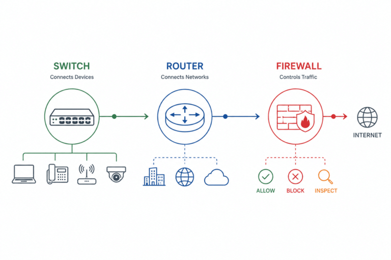
Use a switch to connect devices inside a LAN: desktops, servers, phones, printers, cameras, and access points. Managed network switches add VLANs, link aggregation, access control, monitoring, PoE, and other operational features.
Use a router when traffic must move between IP networks, sites, WAN services, or the internet. Enterprise routers may also provide NAT, VPN, SD-WAN, QoS, and security services, but those capabilities depend on the platform and software.
Do not design a new production LAN around a hub. A hub may still appear in a legacy segment, a controlled teaching lab, or a specialized visibility setup where repeat-to-all behavior is intentional. For ordinary endpoint connectivity, a switch provides full-duplex links, independent forwarding, and manageable segmentation.
Can a Layer 3 Switch Replace a Router?
A Layer 3 switch can replace a router for some internal routing jobs, especially inter-VLAN routing in a campus LAN. It cannot be assumed to replace every WAN or edge router.
Make the choice from the required interfaces and services: WAN handoffs, NAT, VPN and encryption scale, SD-WAN, route scale, buffering, internet-edge policy, hardware redundancy, and support. Some switches can run sophisticated routing; some routers forward in specialized hardware. “Switch equals ASIC, router equals CPU” is not a reliable modern boundary.
Frequently Asked Questions
Does a router use MAC addresses?
Yes, when it sends or receives over Ethernet. The router chooses a path using the destination IP address, then uses a next-hop MAC address to build the outgoing Ethernet frame. MAC addresses change at routed hops; IP addresses normally remain end-to-end when NAT is not used.
Does a switch need an IP address?
A basic Layer 2 switch does not need an IP address to forward Ethernet frames. A managed switch normally has an IP address for administration, telemetry, and services. A Layer 3 switch also uses IP interfaces when it routes.
Can a router replace a switch?
An integrated home gateway may include switch ports, but a routing function does not provide the port density and Layer 2 access features of a dedicated switch. In a business LAN, switches connect endpoints and routers connect networks; one appliance can contain both functions.
Why is a hub slower than a switch?
A hub gives all ports one shared half-duplex segment, so devices contend for the same transmission opportunity. A switch gives each port a separate link and forwards known unicast frames only where needed. Modern full-duplex switched links can transmit and receive simultaneously without CSMA/CD collisions.
Do switches always forward only to the destination port?
No. A known unicast normally goes to the learned egress port. Broadcast and unknown-unicast frames are flooded within the VLAN, and multicast handling depends on the switch’s learned state and configuration.