Fiber Optic Color Code Chart: TIA-598 for 12, 24, 48, and 144 Fibers
Quick answer: The TIA-598 color sequence is blue, orange, green, brown, slate, white, red, black, yellow, violet, rose, aqua. Those twelve colors identify a fiber’s position inside its buffer tube, and the same twelve identify a buffer tube’s position inside the cable, so a fiber in a high-count cable is located by reading tube color first and fiber color second. The chart cannot tell you how the cable in front of you is built. Fibers per tube, how many tubes are active, and how positions past 12 are marked come from the jacket print, the project documentation, and the manufacturer’s cable construction sheet.
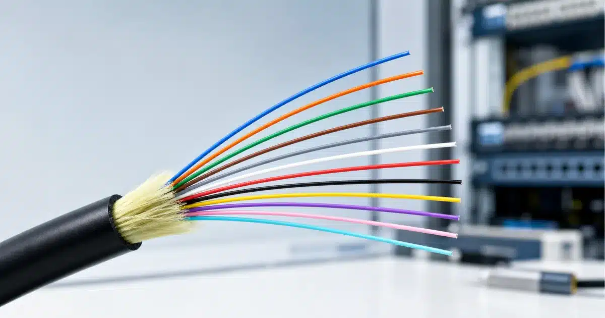
The twelve-color sequence identifies position. It does not identify fiber type, performance, or polarity.
The TIA-598 12-Color Sequence
For an installer tracing a strand in a splice enclosure, or a data center technician checking a trunk before it is terminated, this is the entire lookup.
| Fiber Position | Standard Color | Abbreviation |
|---|---|---|
| 1 | Blue | BL |
| 2 | Orange | OR |
| 3 | Green | GR |
| 4 | Brown | BR |
| 5 | Slate (gray) | SL |
| 6 | White | WH |
| 7 | Red | RD |
| 8 | Black | BK |
| 9 | Yellow | YL |
| 10 | Violet | VI |
| 11 | Rose (pink) | RS |
| 12 | Aqua | AQ |
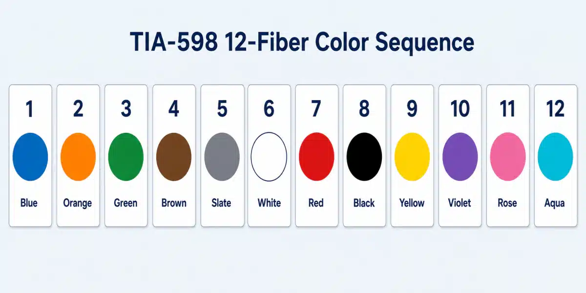
TIA-598 positions 1 through 12. White is outlined in the illustration so it remains visible.
Sequence and abbreviations follow the identification table in ANSI/TIA-598-D, approved July 2014. The standard’s names for positions 5 and 11 are slate and rose; crews often say gray and pink, while the printed abbreviations remain SL and RS.
The position number is an index and nothing else. In this individual-fiber table, blue does not mean single-mode, aqua does not mean OM3, and violet carries no wavelength, data rate, reach, or polarity. Color identifies the fiber’s position; the cable print and product documentation identify the link’s other properties.
Color is also not the only permitted marking. TIA-598-D allows identification by printed legend or printed block coding in place of ink color, where the legend carries the position number, the color abbreviation, or both. A single-fiber cable may leave its fiber natural and uncolored, and a duplex pair may use blue and orange, blue and natural, or natural and natural with a tracer. A cable that shows no obvious color coding is not automatically an unmarked cable.
How Fiber and Buffer Tube Colors Work Together
Twelve colors identify twelve positions. In a common TIA-coded loose-tube cable with more than 12 fibers, the sequence is applied at two levels: first to the buffer tube, then to the fiber inside it. Ribbon, slotted-core, and other cable designs may use a different physical grouping or fixed-position method, so the construction sheet remains authoritative.
Fiber Position Inside a Buffer Tube
Inside a given buffer tube, the first fiber is blue, the second orange, and the count runs to the twelfth in aqua. That is the coordinate most people mean when they search for a strand color code. The standard and nearly all cable documentation use fiber for the glass itself; strand is jobsite and search-box shorthand for the same thing, and this article follows the standard.
Buffer-Tube Position Inside the Cable
The tube’s color states where that tube sits in the cable, using the same twelve colors in the same order. TIA-598-D applies its identification table to fibers, units, and groups. A unit may be a buffer tube, ribbon, thread-tied bundle, or slot in a slotted core; a group is a collection of units.
Where fibers are identified by fixed position, as in some ribbon and slotted-core designs, the color sequence may be preferred practice rather than the sole identification method. Tube count, active tubes, filler rods, layer arrangement, starting tube, and counting direction are construction decisions, not facts that can be inferred from total fiber count.
Calculating the Overall Fiber Number
Assume for the moment that every buffer tube in the cable contains 12 fibers. Under that assumption only:
Overall fiber number = (tube position − 1) × 12 + fiber position
- Fiber 17 sits in tube 2, position 5: an orange tube, slate fiber.
- Fiber 36 sits in tube 3, position 12: a green tube, aqua fiber.
- Fiber 51 sits in tube 5, position 3: a slate tube, green fiber.
- Fiber 144 sits in tube 12, position 12: an aqua tube, aqua fiber.
Running it the other way is the more common field need. Divide the fiber number by 12 and round up to get the tube position, then subtract the fibers in the tubes below it. Fiber 30 gives a tube position of 3, and 30 minus 24 leaves position 6, so fiber 30 is the white fiber in the green tube.
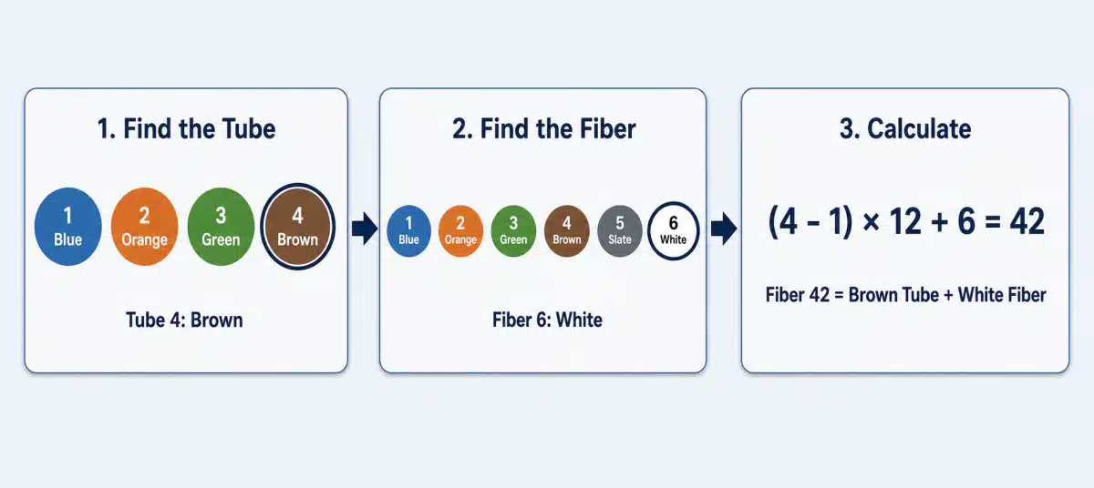
Worked example for a 12-fibers-per-tube construction: fiber 42 is the white fiber in the brown tube.
The arithmetic is only as good as its assumption. A cable with 6 or 24 fibers per tube, an unused tube, or a filler rod counted as a tube returns a wrong fiber number from correct arithmetic, so the fibers-per-tube figure is taken from the construction sheet before the formula is used.
Fiber Color Maps for Common Cable Counts
The maps below are worked examples of common 12-fibers-per-tube constructions, not a specification of how every cable at that count is built.
12-Fiber Cable
One pass through the sequence covers the cable: blue, orange, green, brown, slate, white, red, black, yellow, violet, rose, aqua. That pass may live in a single buffer tube, in a central tube, or in a tight-buffered indoor cable with no loose tube at all. Fiber count alone does not tell you which, and the difference changes how the cable is opened and what the splice tray has to hold.
24-Fiber Cable
One common 24-fiber outside-plant construction uses two tubes of 12 fibers.
| Buffer Tube | Fiber Numbers |
|---|---|
| Blue | 1–12 |
| Orange | 13–24 |
Both tubes run the same internal sequence, so the blue fiber in the blue tube is fiber 1 while the blue fiber in the orange tube is fiber 13. Once a second tube exists, fiber color alone is ambiguous.
48-Fiber Cable
One common 48-fiber layout uses four tubes of 12 fibers each.
| Buffer Tube | Fiber Numbers |
|---|---|
| Blue | 1–12 |
| Orange | 13–24 |
| Green | 25–36 |
| Brown | 37–48 |
A lookup runs in one direction only. To find fiber 42, take the tube position as 4 (brown), subtract the 36 fibers below it, and land on position 6, which is white. Going backwards from a loose white fiber tells you nothing until you know which tube it came out of, so the tube identity is recorded first at every stage of a splice.
144-Fiber Cable
Twelve tubes of twelve fibers is where both levels of the sequence run out together, and the whole map fits in one grid. Rows are the buffer tube, columns are the fiber position inside it, and each cell is the overall fiber number.
| Tube \ Fiber | 1 Blue | 2 Orange | 3 Green | 4 Brown | 5 Slate | 6 White | 7 Red | 8 Black | 9 Yellow | 10 Violet | 11 Rose | 12 Aqua |
|---|---|---|---|---|---|---|---|---|---|---|---|---|
| 1 Blue | 1 | 2 | 3 | 4 | 5 | 6 | 7 | 8 | 9 | 10 | 11 | 12 |
| 2 Orange | 13 | 14 | 15 | 16 | 17 | 18 | 19 | 20 | 21 | 22 | 23 | 24 |
| 3 Green | 25 | 26 | 27 | 28 | 29 | 30 | 31 | 32 | 33 | 34 | 35 | 36 |
| 4 Brown | 37 | 38 | 39 | 40 | 41 | 42 | 43 | 44 | 45 | 46 | 47 | 48 |
| 5 Slate | 49 | 50 | 51 | 52 | 53 | 54 | 55 | 56 | 57 | 58 | 59 | 60 |
| 6 White | 61 | 62 | 63 | 64 | 65 | 66 | 67 | 68 | 69 | 70 | 71 | 72 |
| 7 Red | 73 | 74 | 75 | 76 | 77 | 78 | 79 | 80 | 81 | 82 | 83 | 84 |
| 8 Black | 85 | 86 | 87 | 88 | 89 | 90 | 91 | 92 | 93 | 94 | 95 | 96 |
| 9 Yellow | 97 | 98 | 99 | 100 | 101 | 102 | 103 | 104 | 105 | 106 | 107 | 108 |
| 10 Violet | 109 | 110 | 111 | 112 | 113 | 114 | 115 | 116 | 117 | 118 | 119 | 120 |
| 11 Rose | 121 | 122 | 123 | 124 | 125 | 126 | 127 | 128 | 129 | 130 | 131 | 132 |
| 12 Aqua | 133 | 134 | 135 | 136 | 137 | 138 | 139 | 140 | 141 | 142 | 143 | 144 |
Read down the left edge to find the range owned by each tube. Fiber 60 is still in the slate tube; fibers 61–72 are in the white tube. Fibers 130–132 are in the rose tube, while fibers 133–144 are in the aqua tube. The twelfth fiber of the twelfth tube is aqua in aqua. The same grid works for 96 fibers in 8 tubes or 72 in 6 by stopping at the relevant row, provided every active tube still holds 12 fibers.
Beyond 12 Colors: Tracers, Binders, and Other Identification Methods
Once a cable needs more than twelve of anything at one level, color alone runs out, and the marking methods that take over are where generic charts start to disagree with each other.
Repeated Colors and Tracer Stripes
TIA-598-D carries the twelve base colors through position 48 by adding tracer marks. Positions 13–24 repeat the base colors with a black tracer, except black uses a white tracer. Positions 25–36 use a double black tracer, except black uses double white; a single red tracer is allowed as an alternative, except red uses yellow. Positions 37–48 use a green tracer, except green uses orange; a triple black tracer is another option, except black uses triple white.
The standard also permits other discernible tracer colors when the manufacturer and user agree on them. Manufacturer charts can therefore differ beyond position 12 without changing the base sequence.
Corning’s PGS072 specification shows one manufacturer implementation. In its dual-layer construction, tubes 1–12 use the base colors and tubes 13–24 repeat them with a co-extruded stripe. The count includes only tubes that contain fibers and proceeds from the inside layer outward. Those are product-family rules, so confirm the starting tube and counting direction for the cable in front of you.
Binder Groups and Printed Identification
Units and groups may also be identified by colored binders, printed legends, or printed block codes instead of tube color alone. A printed legend can carry the position number, color abbreviation, or both.
The cable’s own printing carries more than identification numbers. It may include the manufacturer, date, sequential length marks, fiber count, fiber type, and flame rating. When a generic chart and the cable documentation disagree, use the construction sheet and the project specification.
16-Fiber MPO Is a Separate Case
The TIA catalog currently lists ANSI/TIA-598-D as the active base standard, with two published addenda. ANSI/TIA-598-D-1, published in August 2018, adds colors for elements 13–16. ANSI/TIA-598-D-2, published in March 2018, adds the OM5 indoor jacket color.
For a 16-fiber MPO assembly, use the standard revision and assembly documentation cited by the project. Color identification does not establish polarity, keying, or pinning.
Regional and Project-Specific Codes
TIA-598 is the North American baseline used here, not a single worldwide code. IEC/TR 63194:2019 now provides a non-normative guide to major regional color systems. It explicitly does not promote one universal scheme.
Regional documents may use grey, pink, and turquoise where TIA uses slate, rose, and aqua. The names alone do not prove that the position numbering is identical. Confirm the governing standard, project specification, and manufacturer documentation before labeling or splicing.
Fiber Colors vs. Cable Jacket and Connector Colors
Fiber color, jacket color, and connector color are separate identification layers that happen to share parts of the same palette. Treating one layer as proof of another can produce a wrong cable or termination identification.
Cable Jacket Colors
| Cable or fiber type | Common jacket color |
|---|---|
| OM1 62.5/125 multimode | Orange (slate on military cable) |
| OM2 50/125 multimode | Orange |
| OM3 and OM4 50/125 laser-optimized multimode | Aqua |
| OM5 wideband multimode | Lime green |
| OS1 and OS2 single-mode | Yellow |
| Outdoor and OSP cable, any fiber type | Usually black |
ANSI/TIA-598-D covers the indoor and military jacket colors in the table, while D-2 adds lime green for OM5 indoor cable. Outdoor cable is commonly black because carbon black provides UV resistance. Color-compatible UV-resistant materials and colored striping also exist, so black is typical rather than universal and does not identify the fiber type.
Jacket color is therefore a clue, not proof. Settle the fiber type from the jacket print, part number, and datasheet, especially when the choice between multimode and single-mode or the exact multimode grade determines the supported reach. Those decisions are covered in Cisco Multimode vs Single-Mode Fiber and Multimode Fiber Standards: OM1, OM2, OM3, OM4, and OM5.
Connector and Adapter Colors
Connector bodies, boots, and adapters carry a third convention. It describes the termination, and it runs independently of the two color layers inside the cable. The example worth remembering is green, which marks an angled physical contact endface, the polish used where back reflection has to stay low. A green boot identifies the endface geometry and stops there; the mode, the fiber count, the polarity, and the adapter waiting on the other side of the panel all still have to match. The identification and matching rules for each connector family are in Fiber Optic Connector Types: LC, SC, ST, FC, MPO, and MTP Explained.
How to Identify an Unfamiliar Fiber Cable
Work in this order, because each step narrows what the next one has to guess.
- Read the outer-jacket legend and record the manufacturer and part number.
- Obtain the manufacturer’s cable construction sheet for that part number.
- Confirm which color-code standard and revision the cable and the project are built to.
- Confirm fibers per tube, how many tubes are active, whether fillers are present, how many layers there are, and the direction the tube count runs.
- Use the tube color and the fiber color together to locate the fiber you need.
- Verify the mapping at both ends, then record it in the splice documentation or project record.
Steps 2 and 4 provide the construction data the lookup depends on. Skipping either turns the color chart into a guess.
Common Fiber Color Code Mistakes
- Assuming every cable uses 12 fibers per tube.
- Treating TIA-598 as a single worldwide code.
- Counting filler rods as active buffer tubes.
- Confusing fiber, buffer-tube, jacket, and connector colors.
- Misreading slate against white, rose against red, or aqua against blue, especially on faded or dirty coatings.
- Relying on jacket color instead of the printed cable identification.
- Assuming color proves polarity, optical compatibility, or fiber performance.
Counting one filler rod as an active tube shifts every downstream mapping by the tube capacity. In a 12-fibers-per-tube design, that is a 12-fiber offset. Color is a coordinate system for finding one fiber among many; fiber type, grade, condition, and link polarity must be verified separately.