Fiber Optic Connector Types: LC, SC, ST, FC, MPO, and MTP Explained
Quick answer: The main fiber optic connector types used in networks are LC, SC, ST, FC, MPO, and MTP. LC is common on modern switches and transceivers, SC is widely used on patch panels and access networks, and ST and FC are mainly found in older or specialized systems. MPO carries multiple fibers for trunks and parallel optics; MTP® is an enhanced MPO connector made by US Conec. The ports at both ends determine the connector type, while the fiber mode, polish, and channel layout must also match.
What Are the Main Types of Fiber Optic Connectors?
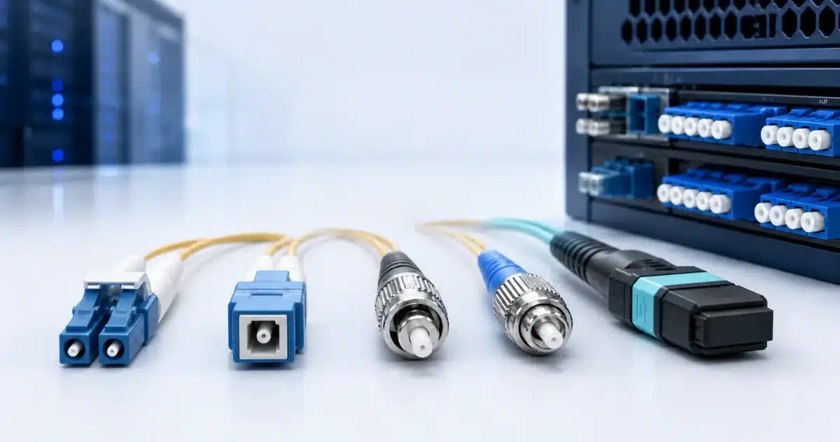
The six types most network installers and buyers encounter are LC, SC, ST, FC, MPO, and MTP. The first four hold one fiber per connector. MPO and MTP place multiple fibers in one rectangular connector.
| Connector | How to recognize it | Fibers per connector | Common use |
|---|---|---|---|
| LC | Small body, 1.25 mm ferrule, latch | 1; often paired as duplex | Switches, servers, SANs, transceivers, and dense patch panels |
| SC | Square body, 2.5 mm ferrule, push-pull coupling | 1; simplex or duplex | Premises cabling, access networks, carrier handoffs, and PON |
| ST | Round body, 2.5 mm ferrule, bayonet twist lock | 1 | Older multimode networks and some industrial or test systems |
| FC | Round keyed body, 2.5 mm ferrule, threaded coupling | 1 | Older single-mode systems, laboratories, and optical instruments |
| MPO | Rectangular body, MT ferrule, push-on coupling | Multiple | Preterminated trunks, cassettes, breakouts, and parallel optics |
| MTP® | An enhanced, branded MPO connector | Multiple | MPO applications that specifically require an MTP assembly |
Connector type describes the physical interface. It does not by itself identify the fiber as single-mode or multimode, determine the link speed, or tell you whether the end face is UPC or APC.
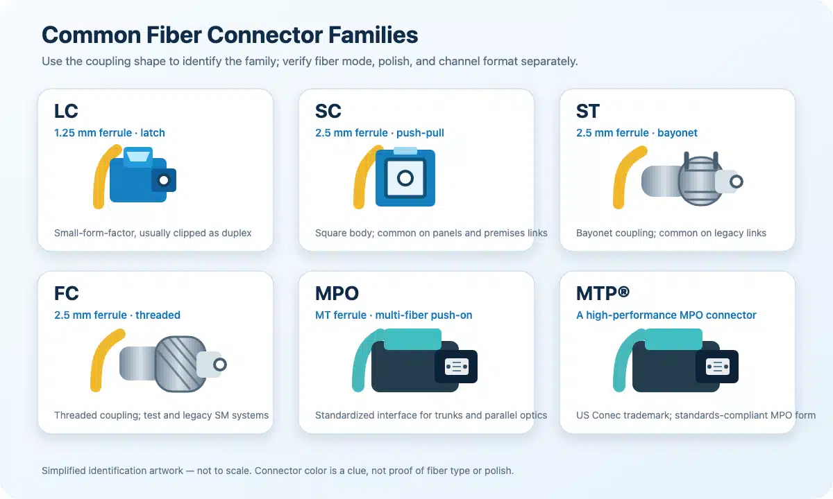
Other connector families serve more specialized needs. CS, SN, and MDC support higher-density duplex applications; MU is a smaller single-fiber format; E-2000 includes a protective shutter; and MT-RJ holds two fibers in one small ferrule. They are not interchangeable simply because their bodies look similar.
What Does Each Fiber Connector Type Mean?
LC Connector
LC is a compact, single-fiber connector with a 1.25 mm ferrule and a latch. Two LC connectors are often clipped together to create a duplex pair, with one fiber transmitting and the other receiving. Its small body makes LC well suited to dense switch, transceiver, line-card, and patch-panel interfaces.
LC can be used with single-mode or multimode fiber and can appear as UPC or APC, depending on the equipment. It is also not tied to one speed. The exact optic determines whether the port needs simplex LC, duplex LC, or another connector entirely.
SC Connector
SC is a single-fiber connector with a square push-pull body and a 2.5 mm ferrule. It is larger than LC and is available in simplex and duplex formats. The larger body uses more panel space, but it can be easier to grip and identify in a distribution frame.
SC remains common in premises cabling, access networks, carrier handoffs, and PON systems. Both SC/UPC and SC/APC versions exist, so the equipment label and documentation must be checked rather than relying on the connector body alone.
ST Connector
ST is a round, single-fiber connector with a spring-loaded 2.5 mm ferrule and a bayonet coupling. It is inserted, pushed, and twisted until the bayonet is fully seated. An incompletely locked ST connector can create an intermittent or high-loss link.
ST was widely used in older multimode premises networks and still appears in legacy campuses, industrial installations, and test setups. It is normally retained because the installed equipment or cable plant already requires it, rather than selected for a new high-density panel.
FC Connector
FC is a round, single-fiber connector with a keyed, threaded coupling around a 2.5 mm ferrule. The screw connection holds the connector firmly, but it takes more time and space to mate than an LC latch or SC push-pull body.
FC is most often encountered on older single-mode systems, laboratory equipment, and optical instruments. The key should be aligned before tightening; a threaded body that feels secure does not guarantee that the ferrules are clean and correctly aligned.
MPO Connector
MPO stands for multi-fiber push on. Instead of holding one fiber, it uses a rectangular MT ferrule to align an array of fibers. Guide pins and matching guide holes control mechanical alignment. Common assemblies may contain 8, 12, 16, or 24 fibers, but the required count comes from the optic or cabling system.
MPO is used for preterminated trunks, cassettes, breakouts, and parallel optical links. It can carry either multimode or single-mode fiber. An MPO connector is therefore not automatically multimode, and it is not automatically faster than LC.
MTP Connector
MTP® is US Conec’s trademark for an enhanced MPO connector design. It complies with the relevant MPO interface standards and is designed to mate with standards-compliant MPO interfaces. In simple terms, MTP is an MPO connector; MPO is the generic standards family. US Conec’s MPO and MTP FAQ explains this relationship and the MT alignment mechanism.
If a bill of materials specifically calls for MTP, preserve the manufacturer and performance requirement. Physical compatibility alone does not prove that an unspecified MPO replacement meets the project’s loss grade, channel warranty, or other system requirements.
LC vs SC vs ST vs FC vs MPO/MTP: Key Differences
The main differences are the number of fibers, connector size, coupling method, port density, and typical installed base.
| Feature | LC | SC | ST | FC | MPO/MTP |
|---|---|---|---|---|---|
| Fibers in one connector | 1 | 1 | 1 | 1 | Multiple |
| Coupling method | Latch | Push-pull | Bayonet twist lock | Threaded | Push-on with guide-pin alignment |
| Ferrule format | 1.25 mm ceramic | 2.5 mm ceramic | 2.5 mm | 2.5 mm | Rectangular MT ferrule |
| Relative panel density | High | Medium | Low | Low | High fiber count per connection |
| Typical role | Modern active equipment and dense panels | Distribution and access networks | Legacy multimode plant | Labs, instruments, and older systems | Trunks, cassettes, breakouts, and parallel optics |
Sharing a ferrule diameter does not make connectors interchangeable. SC, ST, and FC all use a nominal 2.5 mm ferrule, but their push-pull, bayonet, and threaded bodies require different adapters. If the two endpoints differ, a correctly specified hybrid cable—such as LC at one end and SC at the other—can connect them.
Connector size also does not determine fiber mode or speed. LC, SC, and MPO are available on both single-mode and multimode assemblies. A duplex LC optic may carry a high aggregate rate through wavelength multiplexing, while an MPO optic may use several parallel lanes. Cisco’s 400G cabling reference, for example, maps different 400G modules to MPO-16, MPO-8/12, duplex LC, or duplex CS. The exact transceiver—not the speed label alone—determines the connector.
How to Choose a Fiber Connector for Your Application
Start with the ports on the active equipment and the installed patch panels. Do not choose a familiar connector first and then try to make the optic and cable plant fit it.
| Application | Usual starting point | Why | Confirm before selection |
|---|---|---|---|
| Modern Ethernet or SAN switch port | Often duplex LC | Compact and widely used on pluggable optics | Exact transceiver interface, fiber mode, polish, and duplex orientation |
| Bidirectional single-fiber link | Simplex LC or SC | One fiber carries transmit and receive wavelengths | Matched BiDi optic pair, wavelength direction, and polish |
| Premises or access distribution | SC or LC | Common panel and field interfaces | Existing adapter, density, fiber mode, and UPC/APC requirement |
| PON connection | Commonly SC/APC | Supports the specified reflection-sensitive access interface | Exact optical network equipment and APC requirement |
| Legacy multimode plant | ST or SC | Preserves the installed interface | Actual fiber grade, loss budget, and need for a hybrid lead |
| Laboratory or older single-mode system | FC, SC, or LC | The instrument port controls the reference lead | Connector, polish, reference method, and launch/receive lead |
| Parallel optical link | MPO/MTP | Carries several optical lanes in one ferrule | Fiber count, pins, key orientation, polarity, and breakout map |
| Preterminated structured trunk | MPO/MTP with cassettes or modules | Consolidates many fibers and speeds installation | End-to-end loss, cassette map, trunk polarity, and jacket rating |
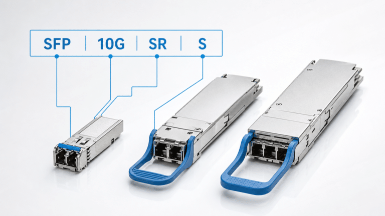
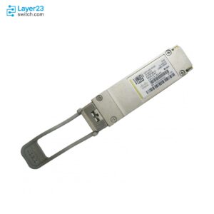
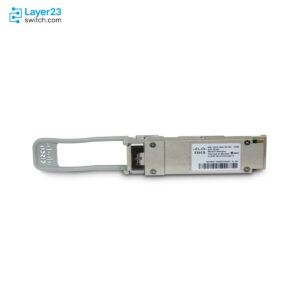
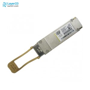
Use MPO or MTP only when the optic exposes a parallel interface or the structured cabling design requires a multi-fiber trunk. Use duplex LC when the optic presents a duplex LC interface. QSFP and QSFP-DD modules can expose MPO, duplex LC, CS, or another connector depending on the optical design, so the host form factor does not settle the cable choice. The SFP, QSFP, and QSFP-DD guide explains the form factors; the exact transceiver data sheet identifies its optical connector.
What Must Match Before You Connect Fiber?
A connector can fit physically while the optical channel is still wrong. Before connecting or ordering a cable, verify the interface at both ends, fiber mode, polish, channel format, and any MPO-specific details.
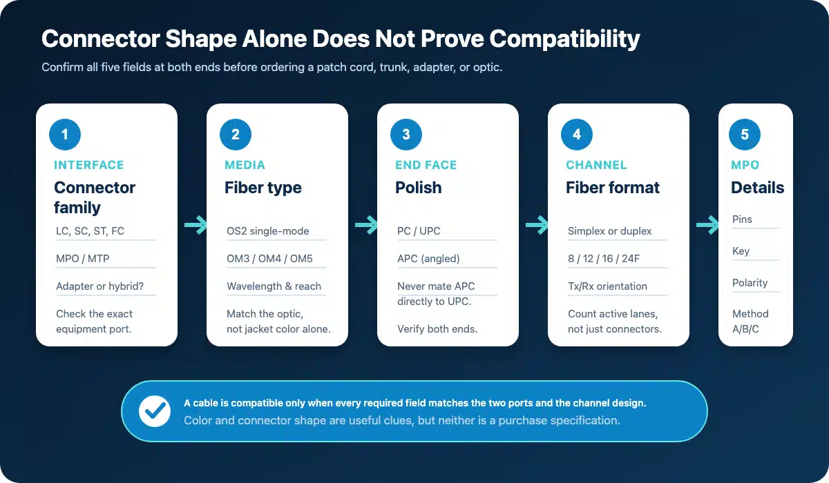
Confirm every applicable field at both ends. Matching only the connector shape is not enough.
A Six-Point Compatibility Check
- Record End A and End B separately. Confirm the connector family and whether each end is simplex, duplex, or multi-fiber. Hybrid cables such as LC-to-SC are valid when the two ports differ.
- Match the fiber mode and grade. LC, SC, and MPO can all appear on single-mode or multimode cable. The optic determines whether the channel needs OS2 or a particular OM grade. Use the single-mode vs multimode fiber guide and the OM1 through OM5 guide if those choices are not yet settled.
- Match UPC or APC polish. UPC and APC describe the end-face geometry, not the connector family. Do not mate APC directly to UPC. The surfaces do not align correctly, loss and reflection increase, and physical contact can damage the polished ends. Fluke Networks documents the angled geometry and damage risk in its APC connector guidance. Color is a clue—green commonly indicates APC—but the label and equipment specification are the source of truth.
- Confirm simplex, duplex, and Tx/Rx orientation. A standard duplex link normally uses one transmit fiber and one receive fiber. A bidirectional optic may use different wavelengths over one simplex fiber. The cable format must match the optics at both ends.
- For MPO, verify the complete fiber map. Record the fiber count, pinned or non-pinned ends, key orientation, polarity method, and any breakout mapping. An MPO-12 assembly is not interchangeable with an MPO-16 interface simply because both use rectangular housings. Evaluate the jumper, adapters, trunk, cassettes, and breakouts as one channel.
- Check the physical route and connector condition. Confirm length, bend management, cable diameter, jacket rating, pulling requirements, and any needed ruggedization. Inspect and clean connector end faces before mating; contamination can cause loss, reflection, or permanent end-face damage.
How to Write a Complete Cable Order Line
A useful order line names End A, End B, polish, fiber type, simplex/duplex format or fiber count, length, and jacket rating. An MPO order also states pinning, keying, polarity, and breakout mapping. If a required field is unknown, the assembly is not ready to quote.
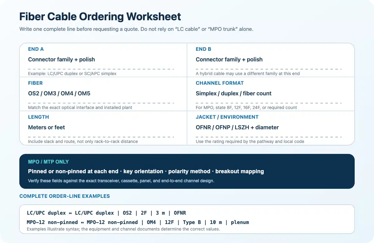
Copy the applicable worksheet fields into the BOM. The examples show syntax, not a substitute for the equipment and channel documentation.
Standard duplex patch lead:
LC/UPC duplex to LC/UPC duplex, OS2, two fibers, 3 m, 2.0 mm OFNR jacket.
Hybrid patch lead:
LC/UPC duplex to SC/UPC duplex, OM4, two fibers, 5 m, OFNP jacket, orientation A-to-B.
Multi-fiber assembly:
MPO-12 non-pinned to MPO-12 non-pinned, OM4, 12 fibers, Method B, 10 m, plenum jacket; verify key orientation and cassette mapping against the channel drawing.
The MPO example remains conditional because cabling systems can express pinning, key orientation, and channel polarity differently. A direct optic-to-optic jumper is also not specified in the same way as a trunk between cassettes. Attach the channel drawing or vendor system reference rather than assuming that “Method B” resolves every transition.
Common Connection and Ordering Mistakes
- Matching the connector family but mixing APC and UPC end faces.
- Ordering simplex LC for an optic that requires duplex, or reversing the Tx/Rx pair.
- Assuming cable color proves single-mode, multimode, or the correct OM grade.
- Ordering MPO-12 for an MPO-16 interface or omitting the fiber count.
- Checking each MPO component separately without validating end-to-end polarity.
- Discovering the jacket rating, breakout length, or bend limitation only after installation.
- Mating connectors without first inspecting and cleaning their end faces.

The shortest reliable rule is: match the exact ports, match the optical channel, and then write the complete cable description. Connector names explain how fibers meet; they do not replace the fiber, polish, polarity, reach, or equipment requirements that make the link work.