How to Configure a Cisco IE1000: Express Setup and Device Manager Guide
Run Express Setup on a factory-default Cisco IE1000 to set its management address, management VLAN, gateway, time source, and a new administrator account. Reconnect to that address in Device Manager, check the switch identity and software release, then build out the VLANs, ports, and, on the PoE models, the power settings. Confirm the installed release before following any older screenshot: IE1000 Software Release 1.9.5 turns on HTTP-to-HTTPS redirection by default, so the browser behavior on your bench may not match the documentation on your screen.
The procedure covers IE-1000-4T1T-LM, IE-1000-6T2T-LM, IE-1000-4P2S-LM, and IE-1000-8P2S-LM. All four run the same Device Manager workflow; only the 4P2S and 8P2S add PoE downlinks and SFP uplinks. If the hardware is still open, compare the IE1000 port and PoE options before anyone writes the configuration plan.
What follows assumes you are a controls or network engineer staging a switch on the bench, or making a planned change inside a maintenance window. Express Setup has no place in an unplanned recovery on a switch that is already carrying production traffic.
Before You Configure the Switch
Cisco classifies the IE1000 as a lightly managed switch, and its configuration interface is the browser-based Device Manager. Cisco’s April 2024 tech note on IE1000 voice VLAN configuration is blunt about what that classification costs you: the switches ship without a console port, and the SSH command line exists only for debugging. Both facts point the same way — on this switch, the management VLAN is the console. Lose it and there is no cable you can plug in to get it back.
First confirm which model is on the bench:
| Model | Data ports and uplinks | PoE configuration in this guide |
|---|---|---|
IE-1000-4T1T-LM | 4 Fast Ethernet downlinks and 1 Fast Ethernet copper uplink | Not applicable |
IE-1000-6T2T-LM | 6 Fast Ethernet downlinks and 2 Fast Ethernet copper uplinks | Not applicable |
IE-1000-4P2S-LM | 4 Fast Ethernet PoE/PoE+ downlinks and 2 GE SFP uplinks | Applies; 120W total PoE budget |
IE-1000-8P2S-LM | 8 Fast Ethernet PoE/PoE+ downlinks and 2 GE SFP uplinks | Applies; 180W total PoE budget |
Those figures come from Cisco’s Industrial Ethernet 1000 Series data sheet, updated May 2023, which lists all four models with their port counts and PoE budgets. The row that shapes the rest of the work is the uplink: the two data-only models leave the cabinet on Fast Ethernet copper, while the PoE models leave on GE SFP and can take fiber. That difference sets how far the cell can sit from its aggregation point without extra hardware, and it is fixed the moment the model is chosen. The 120W and 180W figures are what each switch can pass; how much of it you actually get depends on the power supply feeding it.
Have these on the bench before you press anything:
- The complete switch PID and installed software release, if known
- A computer with a wired Ethernet adapter and JavaScript-capable browser
- A straight-through or crossover Category 5 or better Ethernet cable
- A small paper clip or similar tool for the recessed Express Setup button
- The approved hostname, management VLAN, IP address, subnet mask, gateway, and NTP server
- A new administrator username and strong password
- A record of the intended endpoint and uplink port assignments
This article picks up after the switch has been mounted, grounded, and powered according to its hardware guide. If any of that is still outstanding, work through the industrial Ethernet switch installation checklist for cabinet placement, mounting, grounding, power, and cabling first.
For a documentation-safe example, the steps below use this management plan:
| Setting | Example value | Replace with |
|---|---|---|
| Hostname | IE1K-CELL-01 | The site’s naming-standard value |
| Management VLAN | 10 | The approved management VLAN |
| Switch address | 192.0.2.10/24 | An unused address in the management subnet |
| Default gateway | 192.0.2.1 | The router for that subnet |
| NTP server | 192.0.2.20 | The approved reachable time source |
192.0.2.0/24 is a documentation range, which is why it is safe to print here and useless on a real network. Swap in the site’s own values before anything gets typed into the switch.
If the switch already holds a configuration, stop short of Express Setup. Write down its current address, management VLAN, port assignments, active software image, and whatever backup exists, then get in through the existing management path or an approved recovery procedure. A factory reset can erase the only surviving record of how the switch is wired.
Step 1: Prepare the Switch and Configuration Computer
Stage the switch off the production network. An unknown VLAN, a duplicate address, or the temporary DHCP service that Express Setup starts can all reach live equipment if the uplink is already patched.
- Disconnect all data links from the switch.
- Apply power according to the exact model’s installation guide and wait for startup to complete.
- Configure the computer’s wired Ethernet adapter to obtain an address automatically.
- Temporarily disable Wi-Fi, VPN, and proxy paths if they send browser traffic away from the directly connected Ethernet interface.
- Keep the management values in view so the final address gets recorded before the session ends.
Give the computer exactly one usable path to the setup subnet. With Wi-Fi and Ethernet both live, the browser can take the wrong route while the cable and the port LED look perfectly healthy — the symptom looks like a dead switch and is really a routing decision on your laptop.
Step 2: Enter Express Setup Mode
Express Setup and the factory reset share the same recessed button. The only thing separating them is how long you hold it down.
- Make sure the switch has completed startup and no data ports are connected.
- Insert the paper clip into the recessed Express Setup button for approximately one to two seconds.
- Release it when the Express Setup LED begins flashing green.
- Connect the configuration computer to port
Fa 1/1. - Confirm that the port LED is active and that the computer receives an address.
While Express Setup is running, the switch acts as a small DHCP server. The Running Express Setup chapter of Cisco’s IE 1000 hardware installation guide states that the directly connected computer should receive 192.168.1.1. That service belongs to Express Setup alone; once the switch is configured and power-cycled, it stops handing out addresses, which is why the same laptop settings will not get you back in on the second visit.
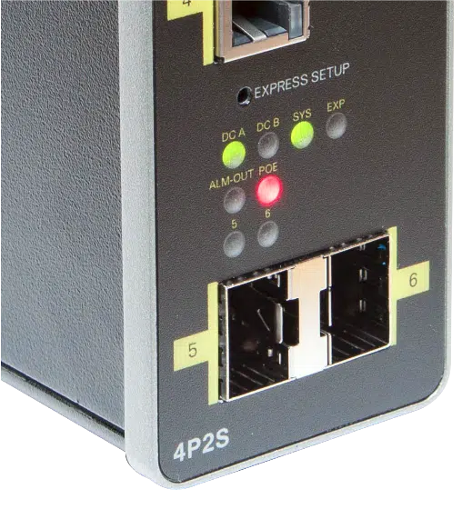
The recessed Express Setup button and status LEDs on an IE1000 PoE model. Confirm the exact front-panel layout on the installed PID.
Let go of the button as soon as the LED flashes; holding it while you wait for the browser is the mistake to avoid. The same chapter documents a 15-to-20-second hold as the factory-reset action, so a patient press on a configured switch wipes it.
Step 3: Open Express Setup and Assign the Management Settings
With the computer connected to Fa 1/1, open a browser and go to:
http://192.168.1.254
Older software leaves the session on HTTP. Cisco’s Release 1.9.5 notes list secure HTTP redirection as on by default, so from that version the browser jumps to HTTPS on its own. Which behavior you get depends on the release inside the switch, and that is one good reason a screenshot found online is a weak guide to what should be on your screen.
On a factory-default unit, Cisco’s onboarding procedure takes a blank username with cisco as the temporary password. It exists to carry you through this one session and should be gone by the end of it. The blank-username behavior is peculiar to the IE1000 Express Setup flow; the Cisco switch default login reference separates it from other Cisco switch families and from any device that has already been configured.
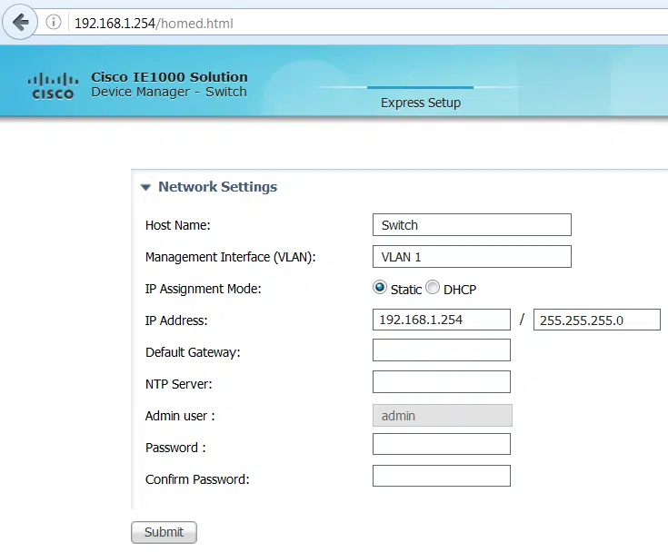
Express Setup collects the hostname, management VLAN, address assignment, gateway, NTP server, and administrator account. The values shown in this older interface are examples only.
Fill the fields from the plan you brought to the bench:
| Express Setup field | What to enter | Why it matters |
|---|---|---|
| Host Name | A unique name such as IE1K-CELL-01 | Identifies the physical switch in monitoring and change records |
| Management Interface (VLAN) | The approved management VLAN | Determines where Device Manager will be reachable |
| IP Assignment Mode | Static or DHCP | Static is predictable; DHCP requires a reliable reservation or lease-discovery process |
| IP Address and Mask | An unused management address and correct subnet mask | Prevents conflicts and defines local reachability |
| Default Gateway | The router in the management subnet | Provides management access beyond the local subnet |
| NTP Server | An approved reachable time source | Makes logs and events useful during troubleshooting |
| Admin User and Password | A new named administrator and strong password | Replaces the temporary onboarding credential |
Two rows in that table are worth a second look before you submit. Keep the static address and the default gateway inside the same subnet; a gateway outside the management subnet leaves a switch that answers only from its own segment. And the installation guide puts the new password at 8 to 31 characters with uppercase and lowercase letters, a number, and a symbol; where the site’s credential policy is stricter, the site policy wins.
Before you select Submit, write down the new management IP, the VLAN, the username, and the port you expect to reconnect through. The moment you submit, the switch leaves Express Setup and the browser session usually dies, because the address and VLAN it now answers on no longer match your temporary setup connection. That drop is what a successful submission looks like, and the note you just made is what gets you back in.
Step 4: Reconnect to Device Manager and Verify the Switch
Move the computer to the new management path:
- If the computer remains directly connected, assign it a temporary address in the new switch subnet. For the example plan,
192.0.2.50/24would be on the same subnet as192.0.2.10/24. - If the switch has been connected to the planned network, use a workstation with permitted access to the management VLAN.
Then browse to the recorded address. With the example plan and software that uses secure redirection, that would be:
https://192.0.2.10
Sign in with the administrator account you created during Express Setup. The temporary factory credential should be dead by now; if it still works, treat the submission as unconfirmed and find out what actually saved.
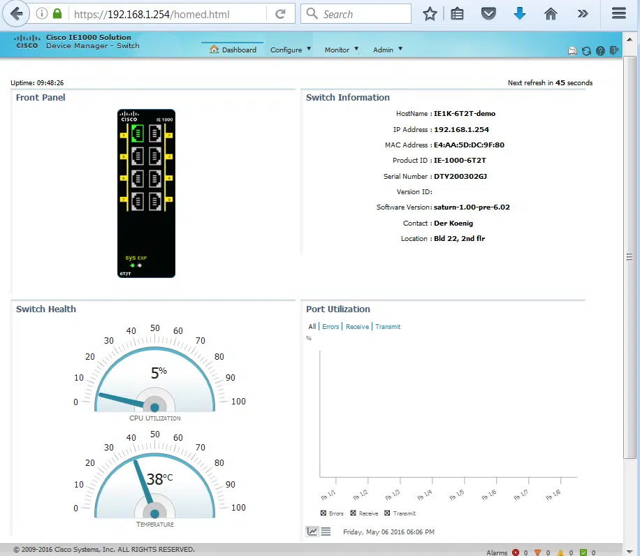
Use the Device Manager dashboard to confirm the switch identity and software state. IP, MAC, serial, and software values in the screenshot are examples.
Check these before changing any VLAN or port behavior:
- The hostname and management address match the change plan.
- The PID matches the physical label on the switch.
- The active software image and displayed version are recorded.
- The expected copper and SFP ports appear on the front-panel view.
- Link state and port utilization are plausible for the connected test path.
- On a PoE model, the displayed PoE-controller information is recorded before any software upgrade is considered.
When Device Manager fails to appear, work through the computer’s address and mask, the management VLAN, the link LED, the URL in the address bar, and whether the installed release is redirecting you to HTTPS.
Step 5: Configure VLANs and Port Roles
Create the VLANs first, assign endpoint ports second, touch the uplink last. That order keeps a management path alive through every step and leaves exactly one change to blame when something stops answering.
Open the Configure menu and locate the Network, Port Settings, VLAN Management, Security, and, on PoE hardware, Power Management areas. Menu wording shifts between software releases, so navigate by what the switch in front of you actually says.
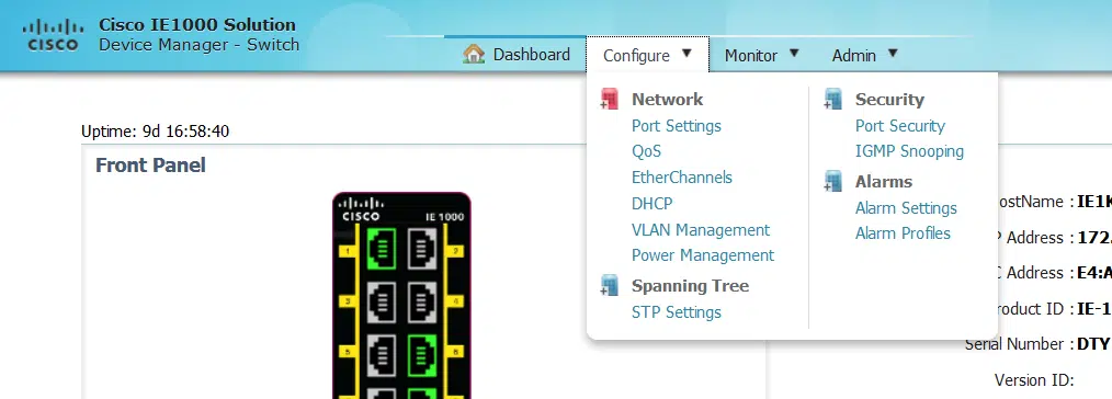
Device Manager groups network, VLAN, port, security, PoE, and system controls under its configuration menus.
For a small machine cell, a plan might separate traffic this way:
| VLAN | Role | Example endpoints |
|---|---|---|
| 10 | Switch management | Device Manager, NTP, monitoring |
| 20 | Control devices | PLCs, HMIs, controllers |
| 30 | Edge or camera devices | Industrial cameras or other approved endpoints |
That split exists to bound the blast radius. A camera or a contractor’s laptop on VLAN 30 has no path to the PLC on VLAN 20 unless the uplink and the upstream router agree to give it one, which is a decision someone has to make deliberately. Build only the VLANs the design calls for; every extra VLAN on an industrial access switch is one more thing to permit or block upstream.
- Open VLAN Management.
- Add the VLAN ID and a useful name.
- Apply and save the VLAN entry.
- Confirm that it appears in the VLAN table before changing ports.
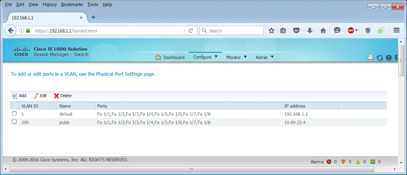
Use VLAN Management to create and review VLAN entries before changing port membership. The displayed IDs and addresses are examples.
Then open Port Settings and assign each port according to its actual role:
- Access: Use for an endpoint that belongs to one untagged VLAN.
- Trunk: Use for an uplink or device that must carry multiple tagged VLANs.
- Hybrid: Use only where the design needs the IE1000’s combination of tagged and untagged traffic. Cisco’s voice VLAN tech note adds that a hybrid port can carry VLAN ID 0 tagging, common in PROFINET environments and unavailable on a trunk port.
The sequence to avoid is moving the management VLAN and the port you are managing through in one unverified batch. Keep a known-good path open, create the VLAN, confirm the upstream switch allows it, and only then move the management interface. Save the uplink for last and check its allowed VLAN list against what the upstream port expects, because a trunk that is right on one end is still down.
After each change, reload Device Manager and test that the endpoint reaches what it should and nothing else. The VLAN table only records what you typed into it.
Step 6: Configure PoE on PoE Models
Only IE-1000-4P2S-LM and IE-1000-8P2S-LM carry PoE/PoE+ downlinks and SFP uplinks. On the data-only 4T1T and 6T2T there is no power to manage, so skip ahead to Step 7.
Before energizing anything, put three numbers side by side:
- The maximum PoE budget supported by the exact switch model
- The power available from the installed supply after the switch’s own consumption
- The maximum and expected draw of every powered device
The headline figure is a ceiling, not an allowance. The data sheet is explicit that the switch and its PoE load together must stay inside the power supply’s capacity, so the arithmetic starts at the supply rating and works down. Four PoE+ ports drawing their full 30W allocation is 120W, the entire published budget of a 4P2S, and that 120W still has to come out of whatever the DIN-rail supply delivers after the switch feeds itself. Heated camera housings are the usual surprise here: their nameplate draw and their cold-morning draw are different numbers, and the plan has to survive the second one.
Open Power Management and review total supported power, used or allocated power, and the per-port state.
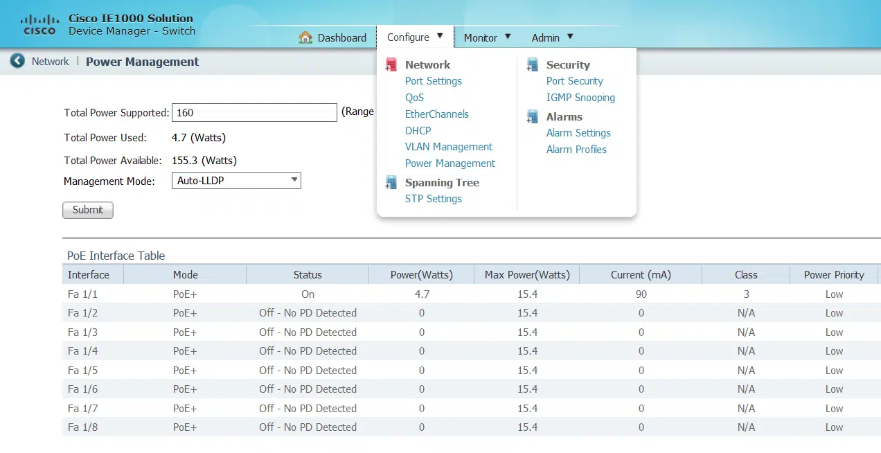
The PoE management page shows total power, allocation mode, and per-port state. Verify every value against the installed supply and powered-device requirements.
Release 1.9.5 documents three PoE management modes:
| Mode | How power is reserved | When to consider it |
|---|---|---|
| Auto-LLDP | Uses the maximum draw negotiated through LLDP | The endpoint supports LLDP power negotiation and the design relies on it |
| Auto-PD Class | Reserves power from the detected powered-device class | The endpoint’s class is the approved allocation basis |
| Static | Reserves the value entered in the maximum-power field | The endpoint requirement is known and a controlled fixed limit is required |
What separates the three modes is who decides the reservation: the endpoint through LLDP, its detected class, or you. LLDP negotiation reserves the least power when the endpoint implements it well, and produces the most confusing allocation table when it does not — which is why a fixed Static value often suits a device whose draw you already know from its data sheet. Whichever mode you choose, connect one device, watch the port detect it, and check the remaining budget against everything else on the plan.
Step 7: Apply Basic QoS and Port Security
Two controls sit near each other in the menu and solve unrelated problems. Priority Port changes how the switch treats traffic arriving from a chosen port; Port Security limits which learned addresses are allowed to stay on one. Both are worth having, and both cause damage when enabled across every port because an example screenshot showed them switched on.
Set a Priority Port for a Defined Critical Endpoint
Priority Port gives traffic received from a selected endpoint, such as a PLC or an IP phone, higher priority than traffic received on other ports. It earns its place once the design has named a genuinely critical device. It is not a generic speed boost, and it changes nothing at all until the switch is congested.
- Open the QoS Priority Port settings.
- Confirm the physical port and connected endpoint from the cable map.
- Enable priority only on the approved port.
- Apply the change and verify both the critical endpoint and other traffic.
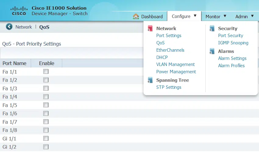
Priority Port can favor traffic received from a designated endpoint. Apply it only from an approved traffic policy.
If prioritizing one port helps one flow and hurts another, the traffic policy is what needs revisiting. Marking a second and third port as high priority walks the switch back to where it started, with more configuration to unwind.
Limit Learned Endpoints with Port Security
The release notes define a port-security user by MAC address and VLAN ID. Once the number of learned users exceeds the configured maximum, the selected violation action determines what happens next.
The trap is the port that legitimately learns more than one address. A machine with an embedded switch inside it, an IP phone with a workstation hanging off the back, and a service outlet an engineer plugs a laptop into all present several MACs to the same port. Watch what a port actually learns before you cap it.
- Open Port Security.
- Select one endpoint port for the initial rollout.
- Set the maximum learned-address count from the actual endpoint design.
- Review the aging behavior and violation action.
- Apply the setting and confirm that the intended endpoint remains connected.
- Document the recovery action before repeating the policy on other ports.
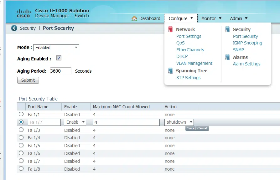
Port Security limits learned endpoints on a port. Verify the maximum count, aging behavior, and violation action before enabling it.
Port Security is one control among several. Segmentation, restricted management access, upstream policy, physical security, and documented change control all still have to exist; a MAC limit on an access port does none of their work.
Step 8: Back Up the Configuration and Update Software Safely
Export the working configuration before treating a software update as routine maintenance. That file is what a restore runs from. Read the active and backup image fields separately: they say what the switch is booting right now, which is not always what the change record assumes.
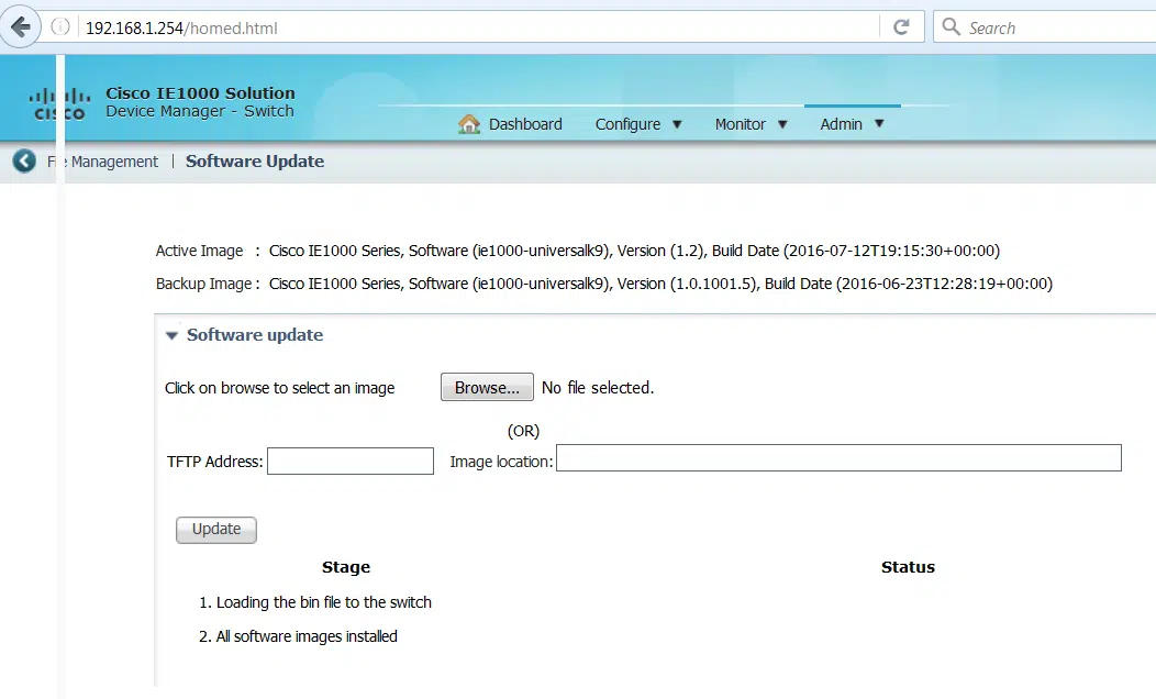
Device Manager provides software-image and backup controls. The image names shown in this older screenshot are not current release recommendations.
Check stock, compare options, or talk with our team.
Use this sequence:
- Export the working configuration and store it outside the switch.
- Record the PID, current software version, active image, backup image, and, on PoE models, PoE-controller type.
- Read the current Cisco release notes for the exact model and hardware revision.
- Pull the correct image from Cisco’s software download service; filenames printed in older articles and screenshots point at releases that have since been superseded.
- Use Device Manager to upload the file locally or through the supported TFTP workflow.
- Keep power stable and leave the switch alone while the image update is in progress.
- After the update, reconnect, verify the active image, and repeat the management, VLAN, uplink, PoE, QoS, and port-security checks.
Cisco’s TechNote on upgrading Industrial Ethernet 1000 switch software, updated April 2021, walks the Device Manager workflow end to end. Check its scope before copying anything out of it: Cisco lists the document against software versions 1.6 and 1.7, and its image table stops at 1.8.2, so every filename in it stops well short of 1.9.5. Pair the workflow with current release notes when you choose an image.
Hardware revision decides the answer on the PoE models. The 1.9.5 release notes state that newer IE-1000-4P2S-LM and IE-1000-8P2S-LM units built around the PD69220 PoE controller require Release 1.9.2a or later, while units with the older PD69200 controller support all available releases. Two switches with identical PIDs on the label can therefore have different valid image lists, so the PoE Controller field on the dashboard belongs in the change record before anyone plans an upgrade or a downgrade.
Verify the Configuration Before Deployment
Configuration pages accept whatever passes their field validation. The bench check below is what tells you the switch works, and it is worth running while the unit is still in front of you.
| Checkpoint | Expected result | If it fails |
|---|---|---|
| Management access | The recorded address opens Device Manager through the expected HTTP/HTTPS behavior | Recheck the computer subnet, management VLAN, gateway, and installed release |
| Device identity | PID, hostname, software release, and active image match the change record | Stop and confirm that the correct physical switch is connected |
| VLANs and ports | Required VLANs exist and every endpoint or uplink has the planned role | Restore the last known reachable port/VLAN state before continuing |
| Uplink reachability | The switch reaches the approved upstream management path without creating a loop | Recheck the uplink role, allowed VLANs, and spanning-tree design |
| PoE operation | Only planned PoE ports are active and total draw remains within the actual supply budget | Check the powered device, cable, allocation mode, per-port limit, and supply capacity |
| QoS and port security | Only approved ports have policies and intended endpoints remain connected | Disable or correct the last policy change on the affected port |
| Time and event records | The configured time source and logs are usable for troubleshooting | Recheck NTP reachability and system settings |
| Backup | A current configuration backup and change record exist outside the switch | Export and verify the backup before deployment |
| Restart check | After an approved restart, the switch returns to the expected address and service state | Use the documented recovery path; do not improvise a reset |
Leave the restart check for the end of staging, once a backup exists and every local change has been saved. On a switch already carrying production traffic, that row waits for a maintenance window.
Troubleshoot Express Setup or Device Manager Access
Match the symptom to the stage that failed. Nearly everything below turns out to be a laptop, an address, or a VLAN, and nearly none of it is solved by a reset.
| Symptom | Likely check | Safe next action |
|---|---|---|
| Express Setup LED does not flash green | The switch is not ready, the press duration was wrong, or the unit is not in the expected state | Confirm startup state and repeat only the short Express Setup action from the current Cisco guide |
| The computer receives no address | Wired adapter is not using DHCP, another interface is preferred, or the cable/setup port is wrong | Check the Ethernet adapter, disable competing paths, and confirm the Fa 1/1 link LED |
192.168.1.254 does not respond | The computer is not on the setup subnet, Express Setup is inactive, or the switch was previously configured | Verify the computer’s assigned address and switch state before considering recovery |
| HTTP changes to HTTPS | The switch is running software with secure redirection enabled | Continue with the release-appropriate HTTPS path and verify the installed version after login |
| Connectivity disappears after Submit | The switch now uses the new address or management VLAN | Move the computer to the new subnet or reconnect through the planned management network |
| The new administrator account fails | The setup was not saved, the wrong switch address is open, or the credentials were recorded incorrectly | Confirm switch identity and the recorded setup values; do not fall back to a factory credential on a configured unit |
| Access is lost after a VLAN or port change | The management port, uplink, or upstream allowed VLANs no longer provide a path | Reverse the last controlled change through a still-reachable path; otherwise stop and use the approved recovery plan |
| PoE controls are absent | The switch is a data-only model or the wrong PID is being managed | Check the physical PID and dashboard before looking for a software setting |
Three conditions mean stop and escalate: the switch carries production traffic, the management path is unknown, or the next step in front of you would erase the configuration. With no local console to fall back on, a destructive reset can convert a reachable problem into a full outage.
Once the commissioning checks pass, save the final configuration, label the management address and connected ports, and file the backup with the device record. And if the port count, uplink type, or PoE budget turns out to be wrong for the job, that is a hardware decision — no amount of Device Manager configuration adds a port or a watt.
Frequently Asked Questions About Cisco IE1000 Configuration
What Is the Default IP Address for Cisco IE1000 Express Setup?
During Express Setup, a factory-default Cisco IE1000 is available at 192.168.1.254, and its temporary DHCP service normally assigns 192.168.1.1 to the directly connected computer. Once you submit the setup, both addresses stop being relevant: use the management IP address you assigned.
Can I Configure a Cisco IE1000 Without a Console Cable?
Yes. The IE1000 does not use a traditional console port for normal configuration; initial setup runs through Express Setup and the browser-based Device Manager. If an already-configured switch has an unknown management address, follow the site’s documented network or recovery path before assuming it is safe to start Express Setup again.
Does Cisco IE1000 Device Manager Use HTTP or HTTPS?
It depends on the installed software release. Older setup documentation may show an HTTP address, while Cisco IE1000 Release 1.9.5 enables redirection from HTTP to HTTPS by default. Record the release shown on the dashboard and expect the browser behavior that goes with it; a redirect on a current release is normal.
Why Can’t I Reach Cisco IE1000 Device Manager After Express Setup?
The connection usually drops because the switch has moved to the new IP address, subnet, or management VLAN you entered during setup. Readdress the computer for the new subnet or reconnect through the planned management network, then open the recorded management address. Check those changes before going anywhere near a factory reset.
Can I Use DHCP Instead of a Static IP for Cisco IE1000 Management?
Yes. Express Setup supports DHCP for the switch management address, provided the address stays easy to identify during maintenance. Use a DHCP reservation or a documented address-discovery process; without one, a documented static address is usually the more predictable choice for an industrial management network.