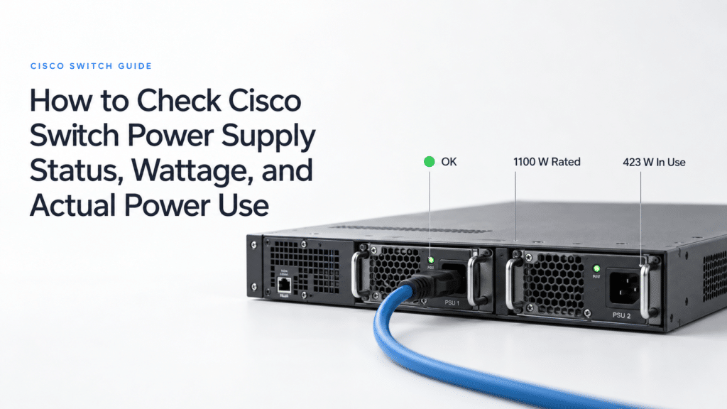
How to Check Cisco Switch Power Supply Status, Wattage, and Actual Power Use
On Catalyst 9200 and 9300 switches, start with show environment power all to see each power supply’s status and rated wattage. On Catalyst 9400, 9500, and 9600 switches, check show environment status or show power detail; on Nexus 9000 switches, check show environment power. The Watts or Capacity figure in those tables is the supply’s rating. Actual power use comes from a Consumed, Input Power, or Actual Input reading, and which of those a switch provides depends on its exact model and software release.
This guide is for engineers investigating a PSU alarm, checking whether a second supply provides real redundancy, or reporting load to facilities. The command excerpts are abridged from Cisco documentation, and none were captured on a Layer23-Switch device. Cisco’s examples show what each field means; actual output, sensor availability, and PSU capacity depend on the switch PID, power supply, input voltage, and software release. Every show command here is read-only, but confirm the device and its power design before acting on a result.
If the supplies and power budget are healthy but one phone or access point has no power, the port-level checks are in our Cisco switch PoE troubleshooting guide.
Power Supply Commands by Platform
| Platform | PSU status | Power-use reading | Mode or budget |
|---|---|---|---|
| Catalyst 9200 and 9200L with replaceable PSUs | show environment power all | show power detail (IOS XE 17.8.1 and later) | show power detail |
| Catalyst 9300 series | show environment power all | show power detail (IOS XE 17.8.1 and later); show environment all for PSU sensors where exposed | show stack-power detail when StackPower is configured |
| Catalyst 9400 | show environment status | show power detail for modules; a metered feed for inlet power | show power detail |
| Catalyst 9500 | show power detail | show platform hardware chassis power-supply detail switch 1 all | PSU rows and planned load |
| Catalyst 9600 | show environment status | show platform hardware chassis power-supply detail switch 1 all; show power detail for modules | show power detail |
| Nexus 9000 (NX-OS) | show environment power | show environment power, where input and output fields exist | show environment power |
In the documentation behind this table, input-side readings appear in only three places: the Catalyst 9500 platform command, which Cisco’s Catalyst 9000 power-supply troubleshooting guide (updated June 2026) says also works on the 9600; the Nexus Actual Input field in the NX-API CLI reference for NX-OS 9.3(x); and the POWin sensor that some 9300 supplies expose. Everywhere else, wall power comes from a metered PDU or feed.
A command missing from one configuration chapter does not prove that a whole family lacks it. The Catalyst 9200 configuration guide for IOS XE 17.14 has no power-consumption section, and Cisco’s Catalyst 9200 command reference for IOS XE 17.15 still documents show power detail, introduced in 17.8.1, with a C9200-48P example. Confirm the running PID and release, then check which fields the device actually returns. Compact Catalyst 9200CX models add one more variable: Cisco’s 9200CX hardware installation guide describes internal fixed supplies on some models and external adapters or PoE-powered uplinks on others, so a two-slot checklist does not fit every 9200CX.
Confirming the Hardware Inventory
Run show version for the switch PID and software release, show switch on a stackable system for member numbers, and show inventory for the PID and serial number of each detected supply. Cisco’s troubleshooting guide lists show inventory first among its verification commands, to confirm that the switch detects the supply. Inventory cannot show whether an empty slot was meant to be filled, so compare the result with the order or asset record and with the physical slots. A Not Present slot may be a planned blank, and a supply the switch cannot read may appear with an Unknown PID, as in the Catalyst 9300 example under Troubleshooting Scenarios.
On a stack, check every member. On a C9300, show environment power all reports the A and B slots by member number, and show environment power switch 3 narrows the output to member 3. Record the member and slot before touching any hardware; Cisco’s Catalyst 9300 configuration guide for IOS XE 17.15 places slot B nearest the outer edge of the switch.
Interpreting Power Supply Status
This abridged C9300 example from Cisco’s troubleshooting guide, with the serial number removed, shows one healthy supply in member 2 and an empty second slot. The output alone cannot say whether slot B was supposed to be populated.
Switch#show env power
SW  PID                 Status       Sys Pwr  PoE Pwr  Watts
2A  PWR-C1-1100WAC      OK           Good     Good     1100
2B  Not Present
2A means member 2, slot A. PID identifies the detected part, Status gives the supply state, and Sys Pwr and PoE Pwr report the system and PoE power paths. Watts is rated capacity, not live consumption: the same C9300 configuration guide shows a Disabled PWR-C1-350WAC still listed at 350 W, and a supply that is switched off draws nothing.
Status Code Reference
| Status on C9300 | Meaning | Next check |
|---|---|---|
OK | Supply present, power good | Confirm the system and PoE paths, and whether the remaining supply could carry the intended load after a failure. |
Not Present | No supply installed in that slot | Compare with the planned configuration; an intentional blank is expected. |
No Input Power | Supply present, no input | Check the feed, cord, PDU outlet and breaker, and PSU LED before suspecting the module. |
Disabled | Supply present with input, but switched off | Check the administrative state and, on StackPower releases that support it, auto-off. |
Not Responding | Supply unrecognizable or faulty | Check inventory and logs, then separate the supply from its slot with controlled physical tests. |
Failure-Fan | The fan inside the supply is faulty | Check the PSU LED and environment alarms, and plan a supply-level investigation. |
Only Not Responding and Failure-Fan point at the supply itself. No Input Power, Disabled, and Not Present describe the feed, an administrative or StackPower action, or the original order, and none of them justifies a replacement on its own. The definitions come from Cisco’s C9300 configuration guide. The Catalyst 9200 guide for IOS XE 17.14 uses No Response for the unrecognizable or faulty state, and modular chassis use other words entirely: on a Catalyst 9400, active and standby are both normal, so read each state against the platform’s power mode.
Measuring Actual Power Consumption
The word “power” labels several different quantities in switch output, and each should be reported with its measurement point.
| Quantity | Typical fields | What it tells you |
|---|---|---|
| PSU rating | Watts, Capacity, Total Capacity | The supply’s specified output under its stated input conditions |
| Reserved power | Budget, Allocated, or a Power Summary Used | Capacity set aside for system components or PoE, which can exceed present consumption |
| Output-side use | Consumed, module Instantaneous, POWout, Output Power, Nexus Actual Output | What the reported components or supplies deliver at that moment; check the field’s scope |
| Input-side use | POWin, Input Power, Nexus Actual Input, or a metered feed | What the supplies draw from an AC or DC feed, depending on PSU type; check whether the figure is per supply or per switch |
The two reporting errors this table guards against run in opposite directions. A reservation quoted as draw overstates the load, and an output-side reading handed to facilities understates wall power by the conversion loss inside the supplies.
Reading show power detail
This abridged IOS XE 17.15 example from Cisco’s C9300 configuration guide covers a three-member stack:
Device# show power detail
...
Power Summary                        Maximum
 (in Watts)    Allocated  Consumed   Available
System Power   1175       315        1670
POE Power      274        85         4180
Total          1449       400        5850
The stack reports 315 W of system use plus 85 W of PoE use, 400 W of consumption at that moment, against 1,449 W reserved. Maximum Available reads 5,850 W, the sum of the listed PSU ratings, including a 350 W supply shown as Disabled elsewhere in the same output. Present wall draw, unallocated PoE headroom, and capacity after a supply failure each need a different figure.
Cisco’s Catalyst 9200 command reference for IOS XE 17.15 shows the same split on a C9200-48P: System Power 230 W allocated and 47 W consumed, PoE 510 W allocated and 199 W consumed, for totals of 740 W allocated and 246 W consumed, with two 1,000 W supplies installed. These are Cisco’s published readings, and other C9200-48P or C9300 installations will report their own figures.
show power inline cannot stand in for a consumption meter. The same command reference defines its Used field as the configured power allocated to PoE ports and Remaining as configured power not yet allocated, and a footnote separates configured power from the real-time power measured by power sensing. On the 9200, show power inline meter, introduced in IOS XE 17.15, displays PoE consumption. For one powered device, use the port-detail fields documented for the model and release. For a switch-level figure, use a documented total Consumed or input reading, since a sum of port reservations measures allocation.
Separating Input and Output Power
Cisco’s note on calculating Catalyst 9300 power consumption (updated July 2025, tested on IOS XE 17.12.4) states that its methods report DC power, measured after AC-to-DC conversion. Some 9300 supplies also expose sensors in show environment all: an example in Cisco’s StackPower configuration and troubleshooting note for the Catalyst 9300 shows PS1 POWin at 198,000 mW and PS1 POWout at 169,000 mW. Check whether the installed supply exposes these sensors before relying on them.
On the Catalyst 9500, Cisco’s troubleshooting guide shows one supply at 131 W Input Power and 118 W Output Power, and the same command works on the 9600. The Nexus 9000 NX-API reference example reports 208 W of actual input and 186 W of actual output across two supplies. Input runs 17 percent above output in the 9300 sensor example, 11 percent in the 9500 example, and 12 percent in the Nexus example; the ratio depends on the supply and its load.
On a Catalyst 9400, show power detail lists Instantaneous values for modules and leaves the fan tray’s field blank. Cisco’s chassis example separately shows “Power consumed by Fantray : 540 Watts” in show environment status, the same figure as the fan tray’s 540 W budget, so a sum of module readings is an incomplete chassis measurement. For facilities capacity, take a measured input-side reading from a supported PSU command or from a meter suited to the AC or DC feed, then assess the planned peak configuration, PoE load, input voltage, and headroom. A single 400 W or 246 W snapshot is neither a design maximum nor a UPS runtime calculation.
Verifying Power Redundancy
Two healthy PSU rows establish present operation, not protection after a supply or feed fails. Protection depends on the intended system and PoE budget, the configured power mode, the output the remaining supplies deliver at the actual input voltage, and whether the feeds are independent. Compare the output-side budget with PSU output capability, and keep input-side meter readings for the electrical and UPS plan.
Fixed-Configuration Catalyst Switches
For a Catalyst 9200 or 9500 with two replaceable supplies, first confirm that the second supply is installed and receiving input, then read the reported power configuration and the model’s hardware capacity rules. Cisco’s C9200-48P example shows two OK supplies while show power detail reports PS Configuration Mode: Non Redundant and PS Operating state: Standalone, so two OK rows are not a redundancy verdict on their own. Check the exact power design of a 9200CX before applying this two-slot procedure.
Input voltage changes the result. Cisco’s Catalyst 9500 architecture white paper (December 2025) rates the 1,600 W AC supply of the 9500 high-performance models at 1,600 W with 220 V input and 1,000 W with 110 V input. Compare the voltage-adjusted output left after a failure with the intended system and PoE requirement. A PDU’s AC watts and a PSU’s output rating sit on opposite sides of the supply, so they cannot be compared directly.
Catalyst 9400 and 9600 Chassis Modes
On the Catalyst 9400 and 9600, show environment status or show power detail shows the configured mode, the operating state, and each supply’s state. Combined mode shares all available supplies with no standby unit, N+1 holds one supply in standby, and N+N places a standby group behind an active group. The configured mode and the operating state use different vocabularies. An example in Cisco’s Catalyst 9400 system management guide for IOS XE 17.14 shows N+N redundant as the configuration and Full protected as the operating state, with four supplies installed, two active, and three listed as currently available. A difference in wording, or an available count below the installed count, is not a fault by itself.
Full protected has a narrow meaning. The same guide defines it against the required budgeted power for supervisors, line cards, and the fan tray, shown as System Power; the separate Inline Power budget is outside that test. PSU output also changes with inlet voltage: the Catalyst 9400 hardware installation guide rates the C9400-PWR-3200AC at 3,200 W on 200–240 VAC and 1,570 W on 100–120 VAC. A 1,670 W system budget, the figure in the Catalyst 9400 example of Cisco’s troubleshooting guide, fits within one such supply on high-line input and exceeds it on low-line input. If line cards show denied while the supplies work, check Power Budget Mode and the supervisor reservation described in Cisco’s troubleshooting guide.
Catalyst 9300 StackPower
On a C9300 configured for StackPower, show stack-power detail shows the power-stack mode, topology, supply count, and allocated budget. Power sharing pools capacity with no reserved supply, and redundant mode subtracts the largest supply from the available budget. The C9300L does not support StackPower. Power stacking is separate from the StackWise data stack covered in our Catalyst 9200 and 9300 stacking guide, and Cisco’s StackPower configuration and troubleshooting note for the Catalyst 9300 covers the mode and cable checks.
On releases with StackPower auto-off, introduced in IOS XE 17.15.2 and 17.16.1, a supply the system has soft-shut reads Disabled, Bad, Bad with nothing wrong with the part. Cisco warns that auto-off does not preserve redundancy: when the stack needs only one active supply, the others stay off, and if that supply fails the whole stack reloads. Read the auto-off setting and the active supply count before treating a Disabled row as a hardware failure.
Nexus 9000 Power Modes
On Nexus 9000 switches, compare the configured and operational redundancy modes, and read each capacity figure against its labeled basis. Total Power Capacity is based on the configured mode, so a mismatch between the two mode lines needs investigating before that number counts as protected capacity. The NX-API CLI reference example has two 650 W supplies, PS-Redundant in both mode fields, 1,300 W of cumulative capacity, and 650 W of capacity under the configured mode; its 186 W actual output and 208 W actual input describe present load. PS-Redundant is N+1 protection against losing a supply. Cisco’s Nexus 9000 high availability and redundancy guide for NX-OS 10.3(x) assigns grid protection to a separate mode, insrc-redundant, with half the supplies wired to each grid, so independent feeds need that wiring checked against the model’s slot-to-grid layout.
Troubleshooting Scenarios
The first scenario uses an example from Cisco’s command reference. The second walks through the readings to take, with no sample output.
No Input Power on One Supply
This abridged example comes from Cisco’s Catalyst 9300 command reference for IOS XE 26.x. The 1A supply has no input, and Cisco’s output shows both its PID and serial number as Unknown:
Device> show environment power
SW  PID             Serial#    Status           Sys Pwr  PoE Pwr  Watts
1A  Unknown         Unknown    No Input Power   Bad      Bad      235
1B  PWR-C1-350WAC   [omitted]  OK               Good     Good     350
Start at the failed input path: the assigned PDU outlet or circuit, the cord, the PSU LED, and related entries in show logging. A narrow show logging | include FRU_PS filter finds the documented supply on/off events, and an empty result does not rule out other power alarms. The 1B row confirms that another supply is running. Whether 1B alone covers the intended system and PoE load is a separate calculation.
If the feed is verified live and the fault persists, follow the physical isolation sequence in Cisco’s troubleshooting guide: test a known-good cord and outlet, then compare with a known-good supply or slot where maintenance conditions permit. Never pull the sole working feed on a production switch. A fault that follows the supply and a fault that stays with the slot lead to different replacement decisions. Where the CLI reports Unknown, take the replacement PID from show inventory if it is readable, from the label on the supply, and from the switch’s supported-parts list; the 235 in the Watts column is no guide to the part.
PoE Budget Unchanged After Adding a Second Supply
Cisco’s troubleshooting guide records cases where a second C9300 supply is detected in Good status but the PoE budget stays at the single-supply figure. The same guide notes that a C9300-48UXM has a 490 W PoE budget with an 1100 WAC power supply, a model-specific budget that can be mistaken for a failed supply. Work through the readings in order:
- Compare both rows of
show environment power allwith the expected hardware.Not Present,No Input Power,Disabled, andNot Respondingeach call for a different check, and a non-OKrow does not by itself mean a hardware fault. - Check
show power inlinefor the available and allocated PoE budget, remembering thatUsedthere means allocated power. On a StackPower stack, readshow stack-power detailfor power-sharing or redundant mode and, on supported releases, auto-off; a reserved or automatically disabled supply changes how installed capacity appears in the budget. - If both supplies work and the mode explains nothing, compare the exact switch PID and PSU combination with Cisco’s hardware PoE table for that model, and check the running release against the software defects Cisco lists. Cisco gives a full power cycle as a workaround in some cases, covering every affected member on a stack, and it needs a planned outage.
If the budget turns out to be a genuine model limit, the answer is capacity planning, covered in our PoE budget planning guide.
Documenting the Result
Record the check time and the source of each number. This compact handoff keeps rating, reservation, and measured use apart:
| Record | Evidence to capture |
|---|---|
| Device identity | Switch PID, software release, stack member, and check time, from show version and show switch where applicable |
| Expected and detected PSUs | Slot, PSU PID and serial if readable, status, LED, and intended slot count, from show inventory, the platform power command, and the asset record |
| Capacity and load | PSU rating at the actual input voltage; allocated system and PoE budget; measured output-side consumption; measured input-side power with feed type (AC or DC) and timestamp |
| Protection | Configured mode and operating state, voltage-adjusted capacity after the stated failure, and the PDU outlets or circuits feeding each supply |
| Diagnosis | Relevant show logging events, physical tests performed, and remaining uncertainty |
Keep input-side measurements and output-side budgets in separate fields, because a correct reading copied into the wrong field still produces a wrong capacity plan. Then close the record with one primary disposition, checked in this order:
- Action required: an expected supply or feed is unavailable, a supply or fan fault persists, or the intended load exceeds capacity after the stated failure. Record whether the evidence points to the feed, supply, slot, mode, or budget.
- Operating, redundancy degraded or unverified: the switch is running, but the expected failover capacity, mode, input voltage, or feed independence has not been established. State what remains to be checked.
- Verified for the stated load: expected supplies and feeds are healthy, the operating mode is understood, and the voltage-adjusted remaining output covers the documented system and PoE budget after the planned failure. State that load and failure assumption, because the verdict does not extend to future growth.
When testing isolates a failed Catalyst supply, match the replacement against the switch PID, the supported PSU list, and the verified PID of the affected unit. Layer23-Switch lists Catalyst 9000 power supplies by model.