C9404R vs C9407R vs C9410R: Which Catalyst 9400 Chassis Should You Choose?
C9404R provides two line-card slots in 6 rack units, C9407R provides five in 10 rack units, and C9410R provides eight in 13 rack units. Start with the number of line cards your deployment needs, including planned additions, then check rack space, power and supervisor performance.
- Choose C9404R when two line cards cover the intended deployment and no additional line-card slot is required.
- Choose C9407R when the card mix or expansion plan requires three to five line-card slots.
- Choose C9410R when the current configuration or a defined expansion requires six to eight line-card slots.
These are starting points for slot capacity. A chassis must also support the intended card combination, supply enough power in the required redundancy mode, and fit the installation site. A larger chassis adds room for cards; the complete configuration determines what those cards can deliver.
C9404R, C9407R and C9410R: Key Chassis Differences
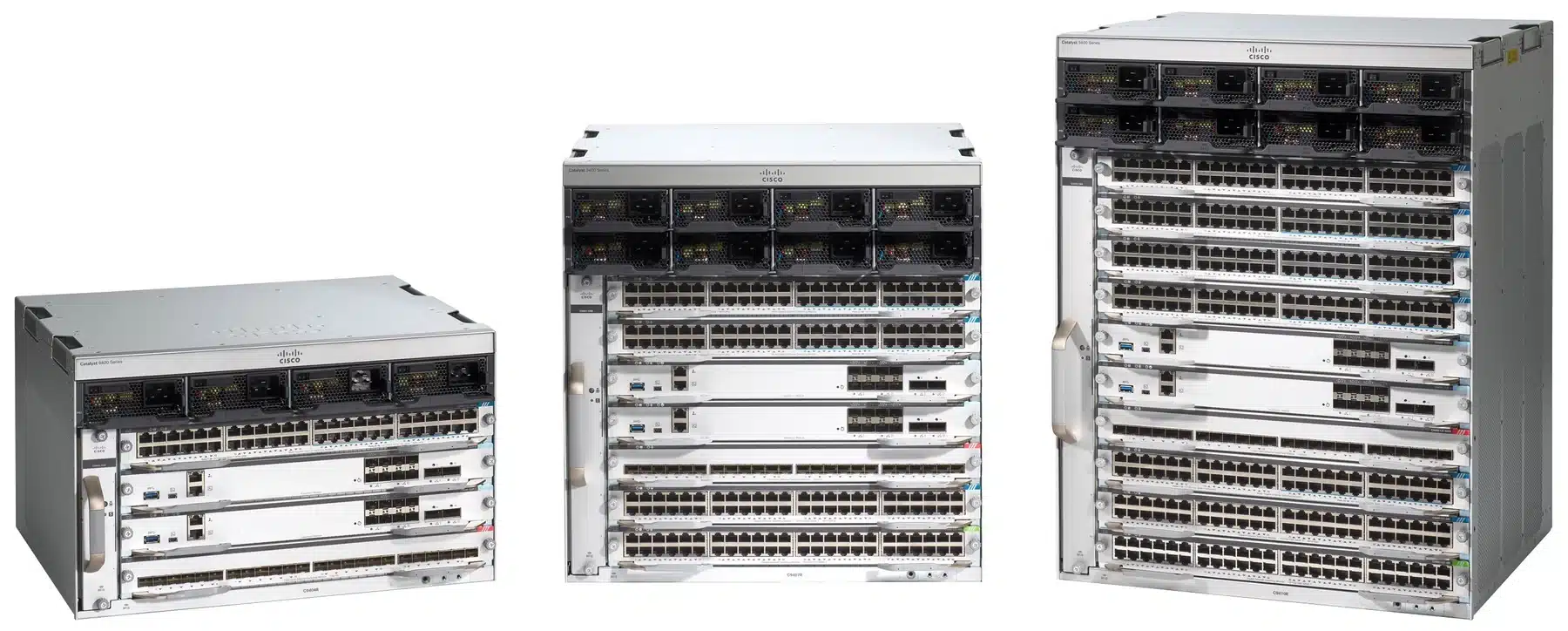
The most useful comparison separates total module slots from slots available for line cards. All three chassis reserve two slots for supervisors.
| Chassis characteristic | C9404R | C9407R | C9410R |
|---|---|---|---|
| Total module slots | 4 | 7 | 10 |
| Dedicated supervisor slots | 2 | 2 | 2 |
| Line-card slots | 2 | 5 | 8 |
| Rack height | 6 RU | 10 RU | 13 RU |
| Power-supply bays | 4 | 8 | 8 |
| Redundant supervisors supported | Yes | Yes | Yes |
| Copper ports with a 48-port copper card in every line-card slot | 96 | 240 | 384 |
An unused supervisor slot cannot take a line card. A C9404R with one supervisor still has only two line-card slots. Conversely, installing a second supervisor does not consume one of those two slots. Redundant supervisors are supported across all three chassis, so that requirement alone does not determine chassis size.
To review shortlisted models alongside other recorded specifications, use the Cisco switch comparison tool. Select the exact chassis models and keep the proposed supervisor, line cards and power supplies alongside the comparison; a chassis entry describes only part of a working switch.
Size the Chassis Around Your Line-Card Requirements
Build a card inventory before selecting the enclosure. The same number of endpoints can require different chassis sizes when interface types, port speeds or the distribution of devices across cards changes.
Count Copper and Fiber Line Cards Separately
Group connections by the interfaces they need, then work out how many cards each group requires. Round up within each group before adding the card counts together. Dividing every connection by 48 can undercount slots when the design mixes copper and fiber cards or uses cards with different port densities.
For example, 96 copper connections require two 48-port copper cards. If the design also requires a separate fiber line card, the total becomes three line cards. C9404R cannot accommodate that combination, even though its all-copper maximum is 96 ports.
First check whether the chosen supervisor’s uplink interfaces cover the required upstream connections. A separate fiber line card should enter the slot calculation only when the port count, speeds or topology actually require it. Record the intended line-card models and quantities so the slot plan can be checked against a real configuration.
Allow for Planned Expansion
Use a simple planning rule:
Required line-card slots = cards needed at installation + additional cards reserved for planned expansion.
Spare ports and spare slots solve different problems. Unused ports on an installed card can accept more devices that need the same interfaces. An empty line-card slot allows another card to be added, potentially with a different interface type. Twenty spare copper ports cannot accommodate a new fiber card.
Tie each reserved slot to an expected change, such as another floor, a planned wireless refresh or additional fiber connections. If those devices fit the installed cards, a new slot may not be necessary. If expansion requires a third card, a fully populated C9404R has reached its slot limit.
C9407R adds three line-card slots over C9404R; C9410R adds another three over C9407R. Decide whether those slots support an identified requirement before accepting the larger rack footprint and the cost of the proposed configuration.
Check Rack Space, Power and Service Access
A slot count establishes which chassis can hold the cards. The installation site determines whether that configuration is practical.
Rack Space and Installation Clearance
Allow 6 RU for C9404R, 10 RU for C9407R or 13 RU for C9410R, then account separately for patch panels, cable management and other equipment in the cabinet. A design that fits on a rack elevation can still leave too little space for cabling or maintenance.
Check the rack’s load rating against the fully configured system. Supervisors, line cards and power supplies add weight beyond the chassis itself. Confirm suitable mounting hardware, cabinet depth and clearance for connectors and cables.
All three chassis use side-to-side airflow. Keep the intake and exhaust paths clear of cabinet walls, cable bundles and neighboring equipment, and check the installation clearances for the selected chassis. Available rack units alone do not confirm that cooling is adequate.
Power-Supply Bays and Available PoE Power
C9404R has four power-supply bays; C9407R and C9410R each have eight. The shared bay count matters when comparing C9407R with C9410R: moving to eight line-card slots does not add more power-supply positions.
Available Power over Ethernet (PoE) depends on the installed power supplies, site input voltage, system consumption and selected redundancy mode. Check the budget with all planned cards installed and with the endpoint load expected after expansion. For AC installations, confirm the output available at the actual site voltage instead of assuming the power supply’s highest rating applies.
Define the failure condition the design must tolerate, such as loss of a power supply or an input circuit, and confirm that the remaining configuration can support the required load. Extra ports have limited value if their devices cannot remain powered under that condition.
For the endpoint inventory and load calculation, use the Cisco PoE budget planning guide. Carry that demand into the chassis power review together with the site’s circuit and UPS capacity.
Access for Cabling and Component Replacement
Plan the cable routes with the chassis populated. More line cards bring more patch leads, and a dense bundle can obstruct module handles or the space needed to remove a component.
Check access to supervisors, line cards, power connections and the fan tray. The platform provides front access to removable components, with an optional rear service approach for the fan tray. The rack position and cable layout should preserve the access your maintenance plan requires.
How Your Existing Supervisor Affects Chassis Choice
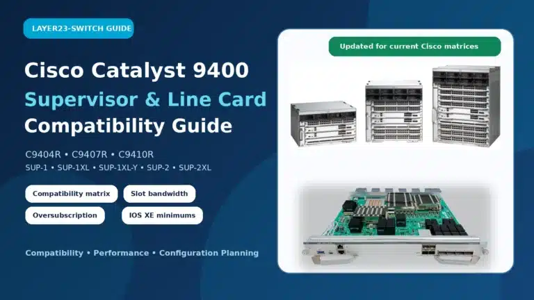
If the project reuses a supervisor, check how its per-slot bandwidth changes in the proposed chassis. C9400-SUP-1XL and C9400-SUP-1XL-Y each provide up to 240 Gbps per line-card slot in C9404R, 120 Gbps in C9407R and 80 Gbps in C9410R. Reusing either supervisor in a larger chassis therefore changes the bandwidth available to each slot, even though more line cards can be installed.
C9400X-SUP-2 supports up to 240 Gbps per line-card slot across all three chassis; C9400X-SUP-2XL supports up to 480 Gbps per line-card slot across all three. These are platform bandwidth limits, not a promise that every card or traffic pattern achieves that rate.
For chassis selection, the decision is whether the intended card mix has enough slot bandwidth with the supervisor being retained or purchased. Confirm the exact supervisor and line-card pairing, any applicable hardware revision requirements, and the Cisco IOS XE release before treating existing modules as reusable. An available physical slot does not establish compatibility.
Which Chassis Fits Your Configuration?
The following hypothetical configurations show how slot demand changes the choice. Each assumes 48-port copper line cards and separately identifies any required fiber card. The slot calculation narrows the chassis choice; power, performance and compatibility still need to pass the checks above.
Compact Access with a Fixed Line-Card Requirement
A deployment needs 96 copper ports. Two 48-port copper cards cover the connections, the supervisor uplinks meet the upstream requirements, and no additional line card is planned.
Slot calculation: 2 copper cards = 2 line-card slots.
C9404R is the smallest chassis that fits this configuration. Both line-card slots are occupied, while the dedicated supervisor positions remain available for the intended supervisor arrangement. If rack space is constrained, its 6 RU height is a practical advantage.
Before selecting C9404R, confirm that the power configuration supports the connected devices and that the two-card limit is acceptable for the deployment’s expected life. A later requirement for another copper or fiber card would change the chassis decision.
Mixed Copper and Fiber with Room to Grow
A deployment needs 96 copper ports and a separate fiber line card for connections that the supervisor uplinks do not cover. The expansion plan calls for one additional copper card.
Slot calculation: 2 copper cards + 1 fiber card + 1 planned card = 4 line-card slots.
C9407R accommodates the plan. Three cards are installed initially, leaving two empty line-card slots. One is reserved for the planned addition; after that card is installed, one slot remains free. C9404R cannot hold even the initial three-card combination.
C9410R would provide more vacant slots, but this four-card plan does not require them. C9407R is the smaller candidate to validate against the 10 RU rack requirement, the selected supervisor’s bandwidth and the power demand after expansion.
High-Density Access with Additional Line Cards
A deployment needs 240 copper ports, a separate fiber line card and room for one additional card in a defined expansion phase.
Slot calculation: 5 copper cards + 1 fiber card + 1 planned card = 7 line-card slots.
C9410R is the only one of the three chassis that accommodates this plan. Six cards are installed initially, leaving two slots empty. After the planned addition, seven of its eight line-card slots are occupied.
C9407R’s 240-port all-copper figure can be misleading for this design: five copper cards already occupy every line-card slot, leaving no position for the required fiber card. The initial configuration alone exceeds its capacity.
Validate C9410R against the 13 RU rack requirement and the completed system’s power demand. If an existing C9400-SUP-1XL or C9400-SUP-1XL-Y is being reused, include its 80 Gbps per-slot limit in the traffic review before approving the configuration.
Once the slot plan is settled, browse the Catalyst 9400 product range for chassis and listed configurations. For a procurement list covering other switching roles as well, the broader network switches category provides the catalog entry point.
For a configured quote, send Layer23-Switch your proposed bill of materials with the chassis, exact supervisor and line-card models, quantities, rack constraints, site power input, PoE demand and planned additions. Have the quote identify the included fan tray, power supplies, power cords, optics, mounting items and required licensing so the price covers the configuration being evaluated.