Cisco Catalyst 9500 Architecture and Design Guide: UADP, Silicon One, SDM, and Deployment Choices
Quick answer: Three forwarding architectures share the Catalyst 9500 name. Earlier base C9500 models use the UADP 2.0 family, current high-performance C9500 models use UADP 3.0, and C9500X models use Cisco Silicon One Q200. Selecting a platform means mapping one specific model to its ports, ASIC path, buffer and queuing model, hardware-table allocation, required features, and supported IOS XE release. A headline throughput figure on its own settles none of that.
The model number opens the design and settles very little of it. Three PIDs from the same series show why. A C9500-32C has two UADP 3.0 ASICs and forwards between them. A C9500-48Y4C has one, and divides its ports between that ASIC’s two cores with a mapping that varies by hardware revision. A C9500X-28C8D has one Q200 ASIC holding six forwarding slices, a Virtual Output Queue (VoQ) architecture, 80 MB of low-latency memory, and up to 8 GB of High-Bandwidth Memory (HBM).
Those differences decide where a packet is buffered, which internal path it takes, how forwarding tables are programmed, which QoS behavior is available, and whether a feature is supported at all. If you are the architect who has to defend the BOM, or the reviewer who has to approve it, the work runs in this order:
exact model → physical port path → forwarding architecture → buffer and queue behavior → SDM and table allocation → feature and release validation → deployment choice
The Catalyst 9500 Family Uses Three Hardware Architectures
Cisco groups the products under one Catalyst 9500 name and one IOS XE operating system, but the forwarding silicon falls into three distinct classes.
| Model or model group | Forwarding architecture | ASIC layout | Native port design | Architectural consequence |
|---|---|---|---|---|
| C9500-12Q, C9500-24Q, C9500-40X, C9500-16X | UADP 2.0 family / UADP 2.0 XL platform class | Model-dependent | Earlier 10G/40G fixed-core designs; C9500-16X supports modular 10G or 40G uplinks | Important for installed-base operations, but not the baseline for a new high-speed core |
| C9500-24Y4C | UADP 3.0 | 1 | 24 × 1/10/25G plus 4 × 40/100G | Fixed 25G aggregation with all ports on one ASIC |
| C9500-48Y4C | UADP 3.0 | 1 | 48 × 1/10/25G plus 4 × 40/100G | Dense 25G aggregation; port-to-core mapping depends on hardware revision |
| C9500-32QC | UADP 3.0 | 1 | 32 × 40G or 16 × 100G | One-ASIC 40G/100G aggregation |
| C9500-32C | UADP 3.0 | 2 | 32 × 40/100G | Ports 1–16 and 17–32 terminate on different ASICs; some flows cross the inter-ASIC links |
| C9500X-28C8D | Silicon One Q200 | 1 ASIC, 6 slices | 28 × 40/100G plus 8 × 40/100/200/400G | Dense 100G/400G, VoQ forwarding, and deep HBM buffering |
| C9500X-60L4D | Silicon One Q200 | 1 ASIC, 6 slices | 60 × 10/25/50G plus 4 × 40/100/200/400G | Dense 50G access to a 400G core-facing design, with the same Q200 forwarding model |
The first row groups four models that share a design era, and they remain in service across a large installed base. That is why an operations question about a Catalyst 9500 and a new-design question about one often have different answers: the same family name covers silicon chosen years apart.
It also explains why a design review framed as C9500 versus C9500X will not get far. The comparison that decides anything is between two specific PIDs and their internal topologies: the dual-ASIC C9500-32C and the single-ASIC C9500-32QC are both high-performance UADP 3.0 switches, and they are materially different machines. Once the ASIC and port layout have narrowed the shortlist, the available Catalyst 9500 models show what those choices cost.
From Front-Panel Port to ASIC: How the System Is Wired
Between the faceplate and the destination port, a packet passes through a chain of physical and logical stages: optic or cable, PHY or clock-and-data-recovery device, serializer/deserializer lanes, the ASIC network interface, forwarding lookup, packet memory, egress scheduling, rewrite, and the destination port. Each of those is somewhere a design assumption can turn out to be wrong.
A single Q200 ASIC serves every C9500X front-panel port
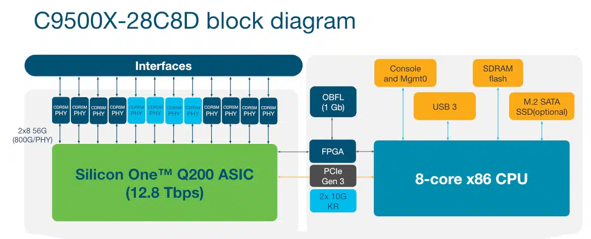
On the C9500X-28C8D, the QSFP28 and QSFP-DD cages connect through CDR5M devices to one Q200 ASIC. The control plane sits alongside that path: an x86 CPU runs IOS XE and programs the forwarding state, while ordinary transit traffic stays in hardware. Because every port terminates on the same Q200, there is no inter-ASIC connection to traverse. Traffic can still cross between internal slices, and those slices are part of one die, communicating through the Q200 crossbar and VoQ system.
The C9500X-60L4D follows the same single-Q200 principle with a different port mix: 60 SFP56 ports and four QSFP-DD ports, per the current data sheet. Port counts belong to the model’s data sheet, never to a specification for the silicon itself and never to an older presentation note.
The C9500-32C divides ports across two UADP 3.0 ASICs
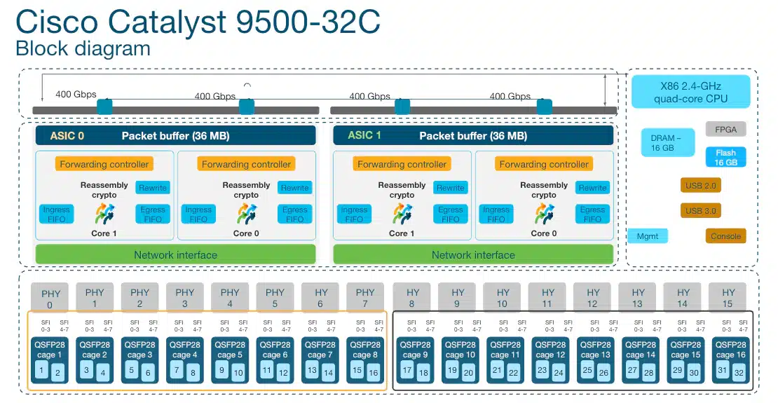
The C9500-32C assigns ports 1–16 to ASIC 0 and ports 17–32 to ASIC 1. A flow from port 2 to port 10 stays local to ASIC 0. A flow from port 2 to port 20 enters ASIC 0, completes the ingress lookup, and then crosses an internal ASIC interconnect before ASIC 1 performs egress processing.
That interconnect lives on the fixed switch’s baseboard, inside the chassis, with no rear-panel cable and no stacking relationship between the two halves. Both the local and the cross-ASIC path are normal, supported forwarding paths. The distinction earns its keep later, when you are reading per-ASIC counters, queue drops, multicast replication, and hardware-resource utilization.
Port locality must be verified on the installed hardware
Even a single-ASIC design can have meaningful core locality. Cisco documents two different port-to-core maps for the C9500-48Y4C, depending on hardware version. The official wording identifies versions below 4 and above 4 but does not clearly settle the boundary value itself — which means a cabling standard written from the documentation alone has a coin flip in it. Check the unit in front of you with show module.
Use read-only commands to establish the real hardware before capacity planning:
show inventory
show module
show version
show platform
show sdm prefer
show platform hardware fed active fwd-asic resource tcam utilization
show platform hardware fed active fwd-asic resource utilization
show platform hardware fed active fwd-asic resource rewrite utilization
Command availability and output fields vary by platform and IOS XE train. Whatever you conclude, write down what it was concluded from: the exact PID, hardware revision, ASIC instances, active SDM template, software release, and the command output itself. That record is what the next capacity question gets answered from.
Check stock, compare options, or talk with our team.
How UADP 2.0 and UADP 3.0 Forward Packets
UADP is Cisco’s programmable campus switching ASIC architecture. UADP 3.0 retains the pipeline concept of UADP 2.0 while increasing forwarding bandwidth, port speed, buffer organization, and hardware-table flexibility.
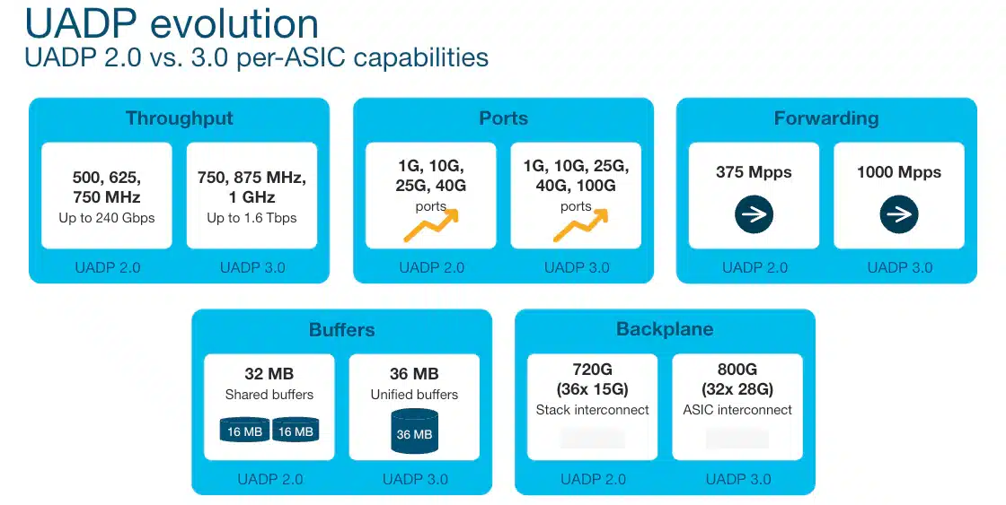
The figure is a per-ASIC generation comparison from the technical presentation, which puts it below the current system data sheet in authority. Check that data sheet before any of it becomes a model-level claim. Cisco’s documents use per-core, per-ASIC, one-direction, full-duplex, hardware-capable, and model-level figures on different pages, each correct within its own scope, so carry the scope with the number whenever you move one between documents.
UADP 2.0 and 3.0 program the FIB differently
The difference that shows up in a capacity plan is how each generation places the forwarding information base in hardware:
| Resource | UADP 2.0 behavior | UADP 3.0 behavior | Why it matters |
|---|---|---|---|
| Exact Match (EM) | Stores exact host routes and directly connected adjacency entries | Part of a shared EM/LPM structure | Host count is only one consumer of forwarding resources |
| Longest Prefix Match (LPM) | Shorter prefixes are placed in the route TCAM | Host and prefix entries share optimized EM/LPM memory | Prefix scale and host scale interact differently from UADP 2.0 |
| Route TCAM | Holds masked prefix entries | Retained mainly for exceptions, including entries that cannot be placed in EM/LPM | A small UADP 3.0 route-TCAM value does not mean low route scale |
| Rewrite and adjacency resources | Store next-hop and egress rewrite information | Separate supporting resources still apply | A route can exist in the FIB while a new adjacency or rewrite cannot be programmed |
| ACL and QoS resources | Allocated separately from basic route lookups | Larger and customizable on high-performance models, within shared budgets | Route, policy, NetFlow, tunnel, and QoS requirements must be sized together |
That table is why show ip route summary answers a software question and leaves the hardware one open. A switch can be down to its last rewrite, adjacency, ACL, QoS, tunnel, or NetFlow entry while the IP route table still looks comfortable. Cisco’s hardware-resource commands report utilization per ASIC, so on a dual-ASIC C9500-32C, read both instances; an average of the two describes a switch that does not exist.
A same-ASIC packet stays in the local forwarding pipeline
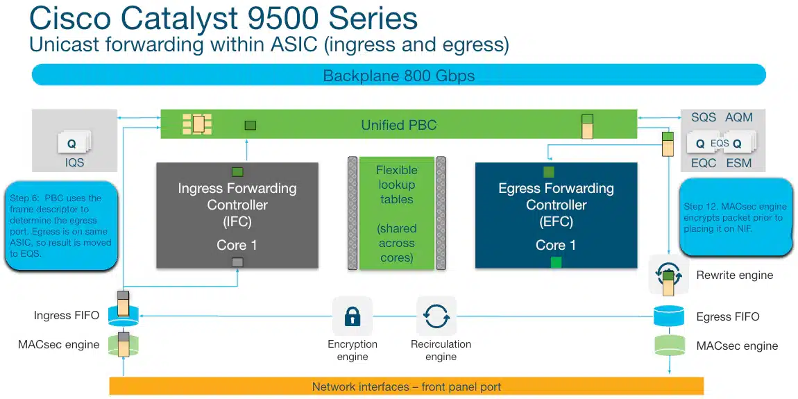
For a local UADP 3.0 flow, the ingress FIFO presents the packet to the Ingress Forwarding Controller and Packet Buffer Complex in parallel. The forwarding controller performs Layer 2, Layer 3, ACL, and QoS lookups and returns a frame descriptor. The local Egress Queueing System schedules the packet; egress forwarding and rewrite functions then prepare it for the destination port.
The split matters when something drops. The descriptor carries the forwarding decision while packet memory holds the packet until the egress scheduler grants transmission, so a lookup failure, buffer pressure, egress queue behavior, rewrite exhaustion, and physical-interface problems all end in a discard by different routes. Diagnose them separately.
A cross-ASIC packet adds an internal transport step
On a cross-ASIC flow, the ingress ASIC still performs the lookup. Its Ingress Queueing System then schedules the packet over the inter-ASIC connection. The destination ASIC receives the packet in its Packet Buffer Complex and continues with egress queuing, forwarding, rewrite, and MACsec processing.
The practical response is to know where the path changes, keep per-ASIC telemetry visible, and validate traffic patterns that are unusually asymmetric or replication-heavy. Port placement is a late-stage tuning input, applied once the model, port speed, resilience design, and supported feature set are settled — never a reason to leave half the chassis empty.
How Silicon One Q200 Changes the Forwarding Model
Q200 runs IOS XE like the rest of the family and forwards by a different method: a multi-slice, credit-scheduled VoQ architecture over a two-tier buffering system.
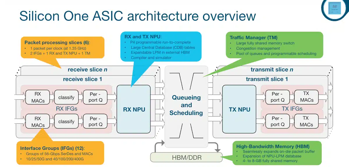
Q200 contains six independently operating forwarding slices, each with its own forwarding I/O resources. The slices connect through an integrated crossbar. Every C9500X front-panel port still maps to the same physical Q200 ASIC, so a slice-to-slice transfer is a different event from the inter-ASIC path in a C9500-32C.
For a simplified unicast walk:
- The receive interface sends the packet to the receive processing path.
- The receive NPU processes the start-of-packet fragment to determine the destination; the packet is stored in the Shared Memory Subsystem (SMS).
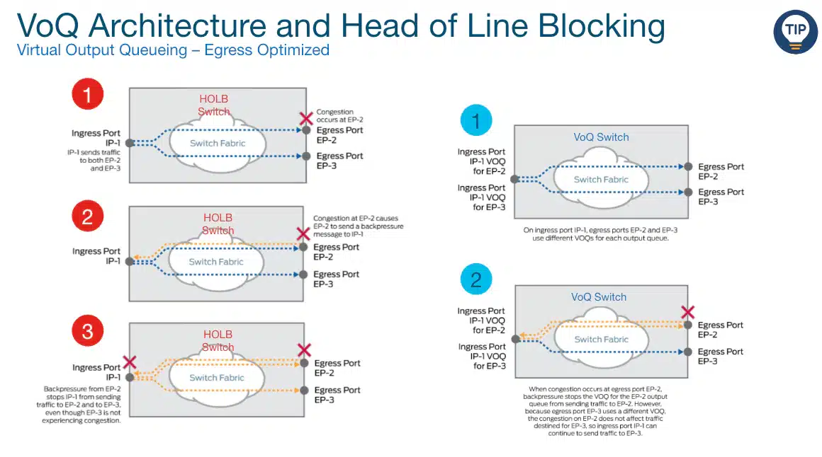
- A packet descriptor is placed in a destination-specific Virtual Output Queue.
- The VoQ requests credit from the destination output queue.
- Once credit is available, the descriptor crosses to the destination slice and output queue, and the stored packet is sent toward the egress interface.
The credit mechanism keeps one congested destination from unnecessarily stalling traffic bound for unrelated, uncongested ones. What it leaves untouched is the arithmetic: oversubscription, congestion, latency, and packet loss all survive it, and a sustained offered load above egress capacity will fill queues until someone decides which traffic loses.
SMS and HBM work as two tiers of one buffer
C9500X provides 80 MB of low-latency SMS memory and up to 8 GB of HBM. All traffic enters SMS first. Under congestion, eligible packets can move dynamically into HBM and return to SMS before transmission. Priority traffic uses SMS to preserve low latency, and the switch—not the operator—controls when packets move between the two memory tiers.
So the 8 GB is a shared pool the switch draws on under congestion, sized to absorb bursts and speed mismatches where extra queuing delay is acceptable. No port owns a slice of it, it promises no packet an indefinite wait, and depth does not stand in for egress bandwidth: a 400G source feeding a 100G port is a 4:1 problem, and HBM only changes how long it takes to become a drop.
The Q200 QoS model supports up to eight traffic classes and eight output queues per port, with valid designs ranging from one priority plus seven normal queues to seven priority queues plus one normal queue. Classification must place traffic into the intended traffic class before the egress policy can schedule it correctly. Familiar Modular QoS CLI terms do not guarantee identical commands or actions across the two platforms, so a working UADP policy needs re-validation on C9500X before it is trusted.
One IOS XE binary, two feature matrices
Cisco can ship the same IOS XE binary across UADP and Silicon One platforms while the forwarding implementation and the release-specific feature matrix stay different underneath. The IOS XE 26.1 release notes, for instance, list C9500X exceptions for NAT, NHRP, GLBP, several NetFlow functions, and several QoS actions, including egress policing and ingress shaping.
That list belongs to one release, and it makes neither UADP universally better nor Q200 incomplete. Read it requirement by requirement against the train you actually intend to run, and read it again when that train changes.
UADP vs Silicon One: Where Each Architecture Wins
The C9500X is the highest-capacity member of the family, and capacity is one input among several. The right platform is the lowest-risk one that satisfies every physical, forwarding, buffering, table, and feature requirement the design actually has.
| Decision factor | UADP 2.0 installed base | UADP 3.0 high-performance C9500 | Silicon One Q200 C9500X |
|---|---|---|---|
| Typical role | Existing 10G/40G core or aggregation | New 25G, 40G, and 100G campus aggregation/core | Dense 50G/100G/400G core and edge services when the feature matrix fits |
| Forwarding topology | Model-dependent UADP ASIC/core layout | One ASIC on 24Y4C, 48Y4C, and 32QC; two on 32C | One six-slice Q200 ASIC on both models |
| Buffer model | UADP shared/unified packet memory, exact capacity by model | Up to 36 MB unified buffer per ASIC | 80 MB low-latency SMS plus up to 8 GB shared HBM |
| Queueing model | UADP queuing and QoS pipeline | UADP queuing with established campus QoS behavior | Ingress VoQ, credit scheduling, and a Silicon One-specific QoS implementation |
| Route-table organization | Separate EM host entries and TCAM prefixes | Shared EM/LPM for hosts and prefixes; TCAM for exceptions | Q200 forwarding tables and custom FIB allocation, with different limits and fields |
| SDM flexibility | Core, NAT, and Distribution in current trains; no custom template | Core, NAT, Distribution, and custom FIB/ACL/4K-VLAN options, release-dependent | Core plus selected custom FIB allocations; no standard NAT or Distribution template and no customizable multicast template |
| Feature confidence | Mature, well-understood behavior in existing deployments; the platform class predates current 25G/100G design assumptions | Broad campus feature set; exact PID and release still govern | Must verify C9500X exceptions in the selected release, especially WAN-edge, QoS, NetFlow, HA, and overlay requirements |
| Strong selection signal | Preserve a supported installed design that still meets scale | Port mix and features fit without needing 400G or HBM depth | 400G, materially larger route/MAC scale, or measured burst absorption justifies Q200 and required features are supported |
| Common selection error | Extending an aging platform because the family name is unchanged | Assuming every UADP 3.0 model has the same ASIC count and traffic path | Buying for 8 GB of buffer or headline Tbps before checking software parity |
Read the bottom two rows together and the table turns into a decision rule: each architecture has one condition that selects it and one assumption that gets people into trouble. UADP 2.0 is selected by an installed design that still meets scale, and undone by loyalty to an unchanged family name. UADP 3.0 is selected by port mix and feature fit, and undone by assuming every UADP 3.0 model is wired alike. Q200 is selected by 400G, table scale, or measured burst absorption, and undone by buying a buffer figure before checking the software matrix.
Compare like-for-like performance numbers
Cisco’s architecture and data-sheet figures can describe an ASIC’s theoretical capability, a model’s enabled port capacity, one direction, both directions, or packets per second above a stated packet size. Each scope is correct where it is published. Mixing them is what produces a wrong number.
The Q200 ASIC is described as supporting up to 12.8 Tbps full duplex, while the current model table lists up to 12 Tbps for C9500X-28C8D and 9.2 Tbps for C9500X-60L4D. The model figures reflect the enabled front-panel design. Use model-level values for BOM comparison, then use ASIC-level documentation to understand the internal architecture. Never multiply a per-core slide value and present the result as guaranteed application throughput.
How SDM Templates Turn ASIC Capacity into Usable Scale
Switch Database Management (SDM) templates allocate finite hardware resources among functions such as MAC learning, unicast and multicast forwarding, ACLs, QoS, NetFlow, security-group entries, labels, and tunnels. Changing the template does not add capacity; it changes which consumers receive more of it.
Template support is different on each architecture class
| Platform class | Standard templates | Custom allocation | Important boundary |
|---|---|---|---|
| Base C9500 | Core, NAT, Distribution in current trains | Not supported | The data sheet retains an SD-Access template row, but its footnote says that static template was removed from IOS XE 17.3.1 onward; confirm the exact release guide |
| High-performance C9500 with UADP 3.0 | Core, NAT, Distribution in current trains | Custom FIB, custom ACL, and custom 4K-VLAN options are supported with release-specific rules | The static SD-Access template was removed from IOS XE 17.3.1 onward in favor of custom allocation; FIB and ACL consumers draw from shared budgets |
| C9500X with Q200 | Core | Selected custom FIB allocations | Standard NAT and Distribution templates and customizable multicast templates are not supported; C9500X uses a different field and budget model |
The current IOS XE 26.x guide documents a 416K FIB resource budget and a 52K ACL resource budget for customizable high-performance C9500 templates, and a separate 608K FIB budget for C9500X. Those are budgets to be divided. Step sizes, default allocations, IPv4/IPv6 width, multicast sharing, NetFlow consumption, labels, hash efficiency, and exception entries all decide how much of a budget converts into usable entries.
Which gives the sizing rule: size the simultaneous feature mix, not a column of independent maximums. A requirement for 200,000 routes, 100,000 MAC addresses, large ACL policy, NetFlow, multicast, and tunnels is approved by showing those numbers coexist on one switch, and a column of separate maximums never shows that.
Before you change an SDM template
Use this workflow before changing SDM:
- Measure the active system. Capture
show sdm preferand per-ASIC forwarding, TCAM, shared-resource, and rewrite utilization. - Build a simultaneous requirement. Include current utilization, expected growth, IPv4 and IPv6, MAC/host/route split, multicast, ACL and QoS policy, NetFlow, SGT, labels, NAT/PBR, and tunnels where applicable.
- Check the exact release guide. Confirm the model supports the desired template and each requested field. A template available on UADP 3.0 may not exist on Q200.
- Review the proposed allocation. With custom templates, inspect the calculated values and priority reductions before committing.
- Plan the reload. Cisco applies the new template after a system reload. In a StackWise Virtual design, verify behavior on both chassis and account for any additional reload condition documented for the release.
- Verify after boot. Run
show sdm preferagain, confirm the active values, verify hardware programming, and repeat the application and convergence tests from the change plan.
An SDM change carries a reload, which makes it a capacity change with an outage boundary attached. Put it in the IOS XE upgrade and change plan whenever the software train or the allocation algorithm moves at the same time. Nothing about the word template suggests a reload, which is exactly why it gets underestimated in change plans.
Match the Architecture to the Deployment
Start with the traffic paths and failure domains in the campus core and distribution design, then pick the fixed switch that implements them. The four deployments below are where the architectural differences above actually change the answer.
Fixed distribution or aggregation
For access blocks terminating many 10G or 25G uplinks, the C9500-24Y4C and C9500-48Y4C give a direct port match on one UADP 3.0 ASIC. A 40G-heavy design, or one needing a smaller number of 100G connections, points at the C9500-32QC. The C9500-32C supplies 32 100G-class ports and brings the dual-ASIC topology with them, so its traffic plan and telemetry have to account for two forwarding instances. Where the 48-port hardware fits, the C9500-48Y4C-A is the line item; the license tier is a separate conversation.
Bursts alone are a weak reason to move to C9500X at this layer. Establish the 50G/100G/400G density, the table scale, or the measured deep-buffer case first, then confirm that the required QoS, NetFlow, routing, overlay, and HA features are supported on the intended release.
Collapsed core
Collapsing core and distribution into one pair concentrates feature breadth and failure recovery into a single tier, and both often matter more there than the highest port speed. Where the design depends on a mature campus feature that is absent on C9500X, a pair of UADP 3.0 C9500 switches can be the safer choice; in a collapsed design that gap costs more than a missing 400G port would. Q200 earns the slot when the same pair also needs 400G, materially larger tables, or deep buffering, and its feature matrix comes back clean.
If the pair uses StackWise Virtual, validate the exact model and release, Dual-Active Detection path, StackWise Virtual links, multichassis EtherChannel layout, control-plane convergence, and upgrade method. That is a separate design session, and the StackWise Virtual design guide runs it.
Three-tier campus core
In a three-tier campus the core has one job: simple, fast, resilient transport, sized for aggregate traffic between distribution blocks. C9500X is a strong fixed-form-factor candidate where 100G/400G density and route scale justify it; UADP 3.0 stays valid where 25G/100G capacity and its feature set already meet the requirement. Once the 28 × 100G plus 8 × 400G shape is settled, the C9500X-28C8D-E puts a price on it.
Modular line cards, greater port expansion, independent fault domains inside a chassis, or a longer growth runway all point away from a fixed 1RU pair. When one of those is on the requirement list, compare a fixed Catalyst 9500 with a modular Catalyst 9600 before the shape of the box is settled.
Campus core plus WAN or edge services
This is the deployment where silicon choice most often overrides port capacity. NAT, NHRP, GLBP, tunnel behavior, MPLS, QoS actions, NetFlow, IPsec, MACsec, and overlay functions each carry their own support status per platform and release, and none of them travel with the words core plus edge. Write the feature checklist first, then test it against the exact PID and release notes.
Against the IOS XE 26.1 exceptions listed earlier, a UADP 3.0 C9500 can be the better edge-services fit even though Q200 has more forwarding and buffer capacity. The other clean answer is to keep the campus core on switching and routing and put WAN services on a purpose-built edge platform.
When a Catalyst 9500 is the wrong form factor
Use a different family when the primary requirement sits outside a fixed campus core:
- Stackable access, copper endpoints, PoE, and access-layer modular uplinks describe a different job; see the Catalyst 9300 versus Catalyst 9500 comparison.
- Modular growth, line-card flexibility, or chassis fault isolation ahead of 1RU simplicity points at the Catalyst 9600.
- A data-center fabric that depends on data-center-specific operations, telemetry, buffering, or ACI/NX-OS behavior belongs in the Catalyst versus Nexus selection guide.
- WAN services, cryptography, service chaining, or interface types dominating the requirement means the answer is a router or a dedicated edge platform.
Validate the Design Before You Buy or Deploy
Run this checklist last. The requirements should already be fixed by the time you compare Cisco switch models side by side; a comparison tool is good at confirming a decision and poor at making one.
| Validation area | Evidence to collect | Approval question |
|---|---|---|
| Exact identity | Full hardware and license PID, hardware revision, power and airflow options | Is the BOM built from the exact model rather than the family name? |
| Port design | Port speeds, breakout mode, optics/cable compatibility, FEC, oversubscription, port-to-ASIC/core map | Can every link run at the required speed on the selected port and optic? |
| Packet path | ASIC count, local/cross-ASIC paths, multicast replication, MACsec path | Are the expected heavy flows and counters mapped to the real internal topology? |
| Buffer and QoS | Burst measurements, speed mismatches, latency budget, queue classes, drop policy | Does the buffer model solve a measured problem, and is the QoS action supported? |
| Hardware tables | Current per-ASIC utilization plus simultaneous three-to-five-year MAC, route, ACL, QoS, NetFlow, multicast, label, and tunnel requirements | Does the active or proposed SDM template support the whole feature mix with margin? |
| Software features | Exact release notes and configuration guide for every required function | Is each feature supported on this PID and release, with usable syntax and scale? |
| High availability | StackWise Virtual support, dual-active detection, link design, convergence and upgrade method | Has failure and upgrade behavior been tested, not inferred from “SSO supported”? |
| Software train | Cisco recommendation, exact-PID download availability, caveats, ROMMON and upgrade path | Is the selected release appropriate for the requirement and hardware? |
| Supply | Stock position, lead time, and availability of the exact PID together with its optics and power options | Can this BOM be delivered complete, on the project’s timeline? |
There is no score at the bottom of that table. A single unanswered row is enough to send the BOM back, because every one of them names a way a switch can arrive correct on paper and wrong in the rack.
As of August 25, 2026, Cisco lists IOS XE 17.15.6 as the recommended release for both C9500 and C9500X, with the caveat that the recommendation is general: confirm that the image is available for the exact PID and supports the required hardware and features. Note the split that catches people out — a 26.x configuration guide can be the best reference for how a feature works without that making 26.x the automatic production recommendation.