Cisco StackWise Virtual Explained: Architecture, Forwarding, and Failure Recovery
Quick answer: Cisco StackWise Virtual combines two supported, directly connected switches into one logical system, with a shared control and management plane and forwarding hardware active in both switches. The StackWise Virtual Link (SVL) carries inter-switch control and required data traffic, while a working, independent dual-active detection (DAD) path identifies two live Active switches after SVL loss. Resilience depends on supported hardware and software, working alternate paths, and sufficient capacity during failures.
This guide follows one C9500 example from normal forwarding through failures and maintenance. For the architectural choice between physical stacking and a virtual pair, see StackWise vs StackWise Virtual.
What Is Cisco StackWise Virtual?
StackWise Virtual lets supported Cisco switches operate as one logical switch or router while retaining two physical forwarding systems. An upstream router or downstream access switch interacts with the logical system; traffic can enter or leave either chassis. Cisco uses this approach in campus aggregation and collapsed-core designs.
Unlike physical Cisco StackWise, which uses dedicated stacking connections on supported access switches, StackWise Virtual uses supported network interfaces for the inter-switch connection.
Our conceptual example has the following components:
| Component | Example design |
|---|---|
| Switches | Two C9500-24Y4C switches, named SW1 and SW2 |
| Software and license | The same IOS XE 17.18.x maintenance version and Network Advantage level on both |
| Inter-switch link | Two 100G physical members forming the SVL |
| Dual-active detection | One separate, directly connected 10G Fast Hello DAD link |
| Network connections | Upstream and downstream EtherChannels with members on both switches |
| Additional endpoint | A service device attached only to SW2 |
Example scope: This is a document-based design walkthrough, not a hardware test or a configuration recipe. It specifies a release family rather than a tested maintenance build or optics bill of materials. Exact software, transceivers, port assignments, and feature combinations must be checked before implementation.
How Do Active and Standby Roles Work in Cisco StackWise Virtual?
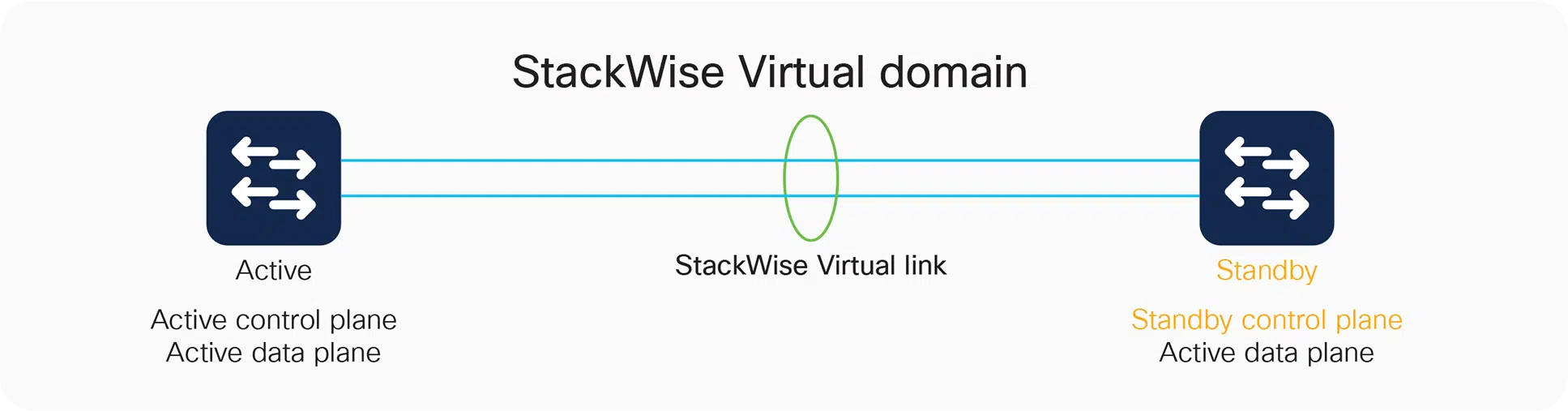
Cisco StackWise Virtual uses one Active control plane and one synchronized Standby control plane, while both chassis forward traffic through their hardware.
One Active Control Plane, Two Forwarding Switches
SW1 is initially Active: it runs the system’s control protocols and manages the configuration. SW2 is Standby for those functions, but its hardware still processes ordinary traffic. A packet entering SW2 does not automatically visit SW1’s CPU before leaving a local port. Cisco’s architecture separates these control and forwarding responsibilities.
This distinction changes how you interpret utilization. Busy interfaces on the Standby chassis are normal. The operational question is whether its control plane is synchronized and ready to assume responsibility if needed.
It also defines a tradeoff: two chassis provide physical redundancy, but they share a logical configuration and software environment. A harmful configuration change can affect the whole system. Assess that shared failure domain alongside the benefits of simpler management.
What SSO and NSF Preserve During a Switchover
Stateful Switchover (SSO) keeps supported state synchronized so that the Standby can take over control. Nonstop Forwarding (NSF) helps forwarding continue along known routes while routing information is restored. Routing-protocol support and neighbor capabilities matter; SSO alone is not proof that every routing session will survive unchanged.
For a design review, separate three questions: Is the backup control plane ready? Does a working physical path remain? Can that path carry the traffic? SSO helps answer the first. It cannot restore a cable attached to a failed chassis or provide missing bandwidth on the surviving uplink.
What Do SVL, DAD, and MEC Do in Cisco StackWise Virtual?
In Cisco StackWise Virtual, SVL carries inter-switch control and required data traffic, DAD detects dual activity, and MEC connects an external device through one EtherChannel spanning both chassis.
SVL: Control Synchronization and Traffic Between Switches
The StackWise Virtual Link (SVL) connects the two switches as members of the logical system. It carries inter-switch control information and business traffic that needs to reach the other chassis. In our example, two 100G physical member links provide the interconnect.
The terminology matters: losing one SVL member link is different from losing the entire SVL. The former leaves another connection available; the latter removes communication between the two members. Treat the SVL as a dedicated system interconnect, not an ordinary trunk that can be routed through an intermediate network.
DAD: Detecting a Dual-Active Condition
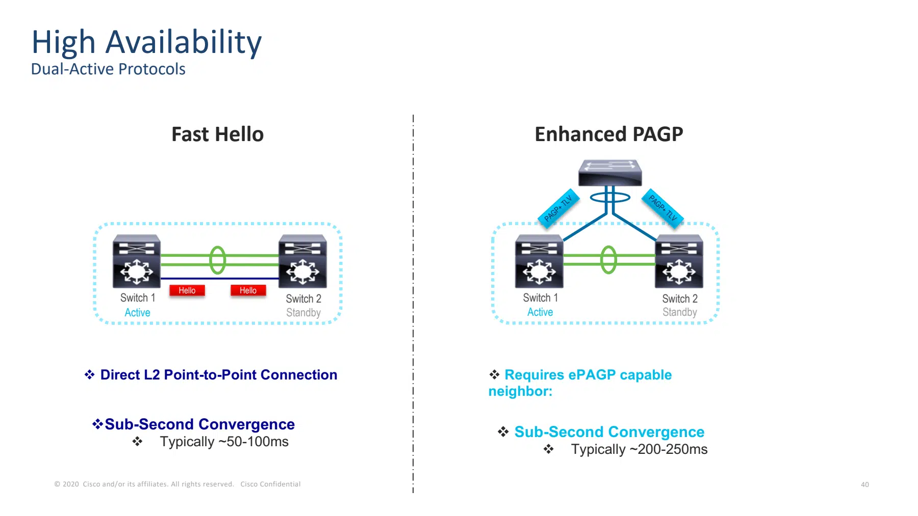
Dual-Active Detection (DAD) provides a way to detect that both switches are claiming the Active role after inter-switch communication fails. Our design uses a separate direct Fast Hello link. Enhanced PAgP is another mechanism, subject to compatible neighbors and platform support.
The DAD link does not carry replacement user traffic when SVL fails. Its purpose is to distinguish “the other switch is still alive and Active” from an actual chassis failure. Cisco describes both detection mechanisms and their requirements in the C9500 StackWise Virtual guide.
MEC: One EtherChannel Across Both Switches
A Multichassis EtherChannel (MEC) combines network-facing links from both chassis into one logical EtherChannel. An access switch can therefore have one bundle with a member connected to SW1 and another to SW2.
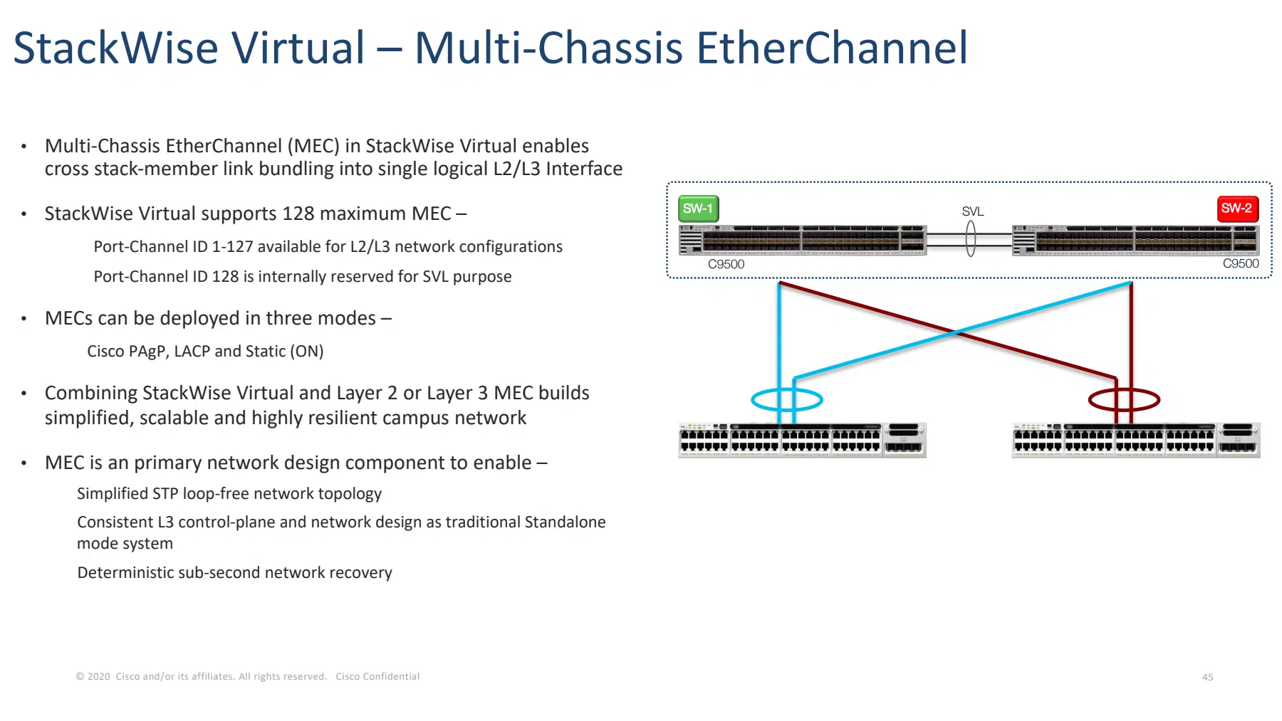
This changes the topology seen by its neighbor: two physical destinations belong to one logical system. For Layer 2, the pair is one bridge and the EtherChannel is one logical connection. That can avoid blocked parallel links in the intended design; it does not make every possible external loop safe or justify disabling STP across the network.
| Connection | Main job | What it does not provide |
|---|---|---|
| SVL | Connect the two system members and carry necessary inter-switch traffic | An independent dual-active detection path |
| Fast Hello DAD | Detect two live Active members through a separate connection | Backup capacity for user traffic |
| MEC | Connect another device through one bundle spanning both chassis | Protection for unrelated single-homed connections |
How Does Cisco StackWise Virtual Forward Packets?
Cisco StackWise Virtual forwards traffic through eligible local exits when available and sends traffic across the SVL when processing or egress requires the peer chassis.
Local Forwarding and Local MEC Members
Suppose an access switch sends a packet to SW1, and the upstream MEC has a usable member on SW1. The packet can be processed and forwarded through that local exit. MEC forwarding favors eligible local members, reducing unnecessary SVL traffic. The same principle applies to traffic entering SW2, even while SW2 is the control-plane Standby.
Consider the reverse direction separately. The upstream neighbor selects its own outgoing EtherChannel member, so return traffic might enter either chassis. “Local forwarding” does not promise that both directions follow identical physical links or that traffic splits evenly between switches.
When Traffic Must Cross the SVL
Now send a packet entering SW1 to the service device attached only to SW2:
- SW1 processes the incoming packet and identifies its destination.
- The required physical exit is on SW2, so the packet crosses the SVL.
- SW2 performs egress processing and sends it to the service device.
The same need arises when SW1 loses all its local exits in an otherwise operational MEC. A surviving exit on SW2 becomes reachable through the SVL. Control traffic and packets requiring software processing on the Active can also cross the interconnect.
These packet paths follow the architecture illustrated in Cisco’s white paper. The design consequence is that a lightly loaded SVL during normal operation may become busy after an external link failure.
Broadcast, unknown-unicast, and multicast traffic needs separate attention. Cisco’s BUM optimization depends on the VLAN’s topology and configured behavior; it does not apply to VLANs with standalone physical ports. A single-homed service can therefore change the assumptions behind an otherwise MEC-only design. Verify the exact behavior rather than assuming BUM always crosses—or never crosses—the SVL.
How Does Cisco StackWise Virtual Handle Link and Chassis Failures?
Cisco StackWise Virtual uses surviving links after member-link failures and a synchronized Standby after Active-chassis failure; if all SVL links fail while both chassis remain alive, independent DAD must still work for the documented dual-active isolation sequence.
A Single SVL or MEC Member Link Fails
If one of the example’s 100G SVL members fails, the other remains available. The pair has lost interconnect capacity and redundancy, but it has not necessarily lost its peer or entered a dual-active state.
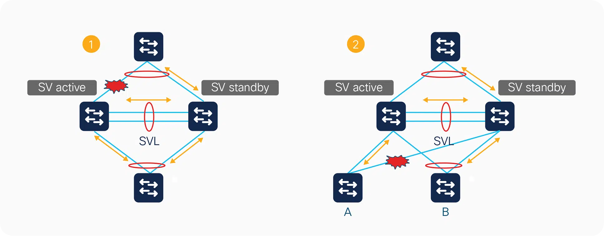
If one MEC member fails, usable members can keep the bundle operational, subject to its configuration, including any minimum-link requirement. Losing SW1’s only local exit may move traffic across the SVL to SW2. Monitor both the external bundle and the interconnect; the bottleneck may appear somewhere other than the failed interface.
The direction of traffic determines which device must select a surviving member. The following two slides show the same failed access-facing link with traffic traveling in opposite directions.
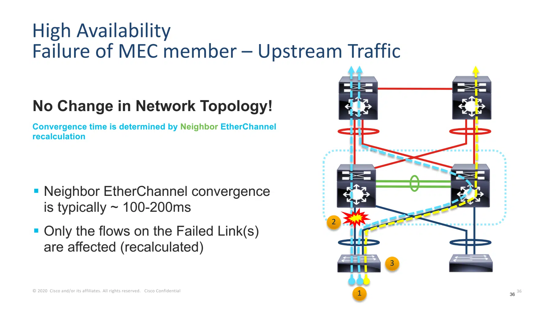
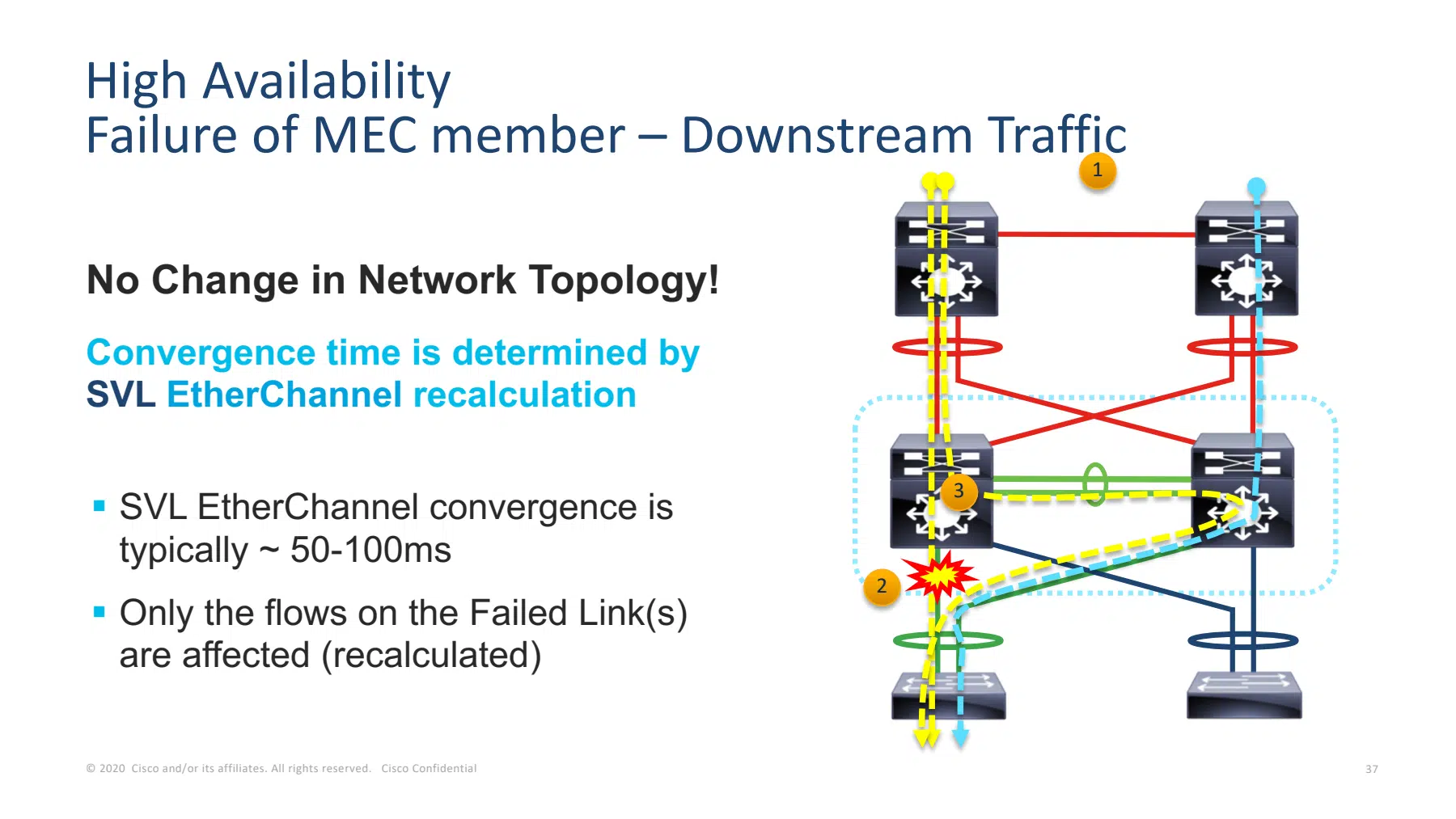
For traffic traveling toward that access switch, the chassis that lost its local exit can instead reach the surviving remote member through SVL. The logical EtherChannel can remain up in both cases, but the physical forwarding path and interconnect load have changed.
An Active or Standby Chassis Fails
If SW2, the Standby chassis, fails, SW1 remains Active. Links and endpoints attached to SW2 disappear, and dual-homed neighbors use surviving connections to SW1. The single-homed service on SW2 is unavailable.
If SW1, the Active chassis, fails, a healthy synchronized SW2 takes over control as well as handling traffic through its surviving interfaces. Neighbors must stop using links to SW1. The service attached to SW2 remains physically connected, although application continuity still depends on its complete network path.
This is why chassis redundancy and endpoint redundancy must be assessed separately. A design cannot preserve access to a device whose only network attachment has failed.
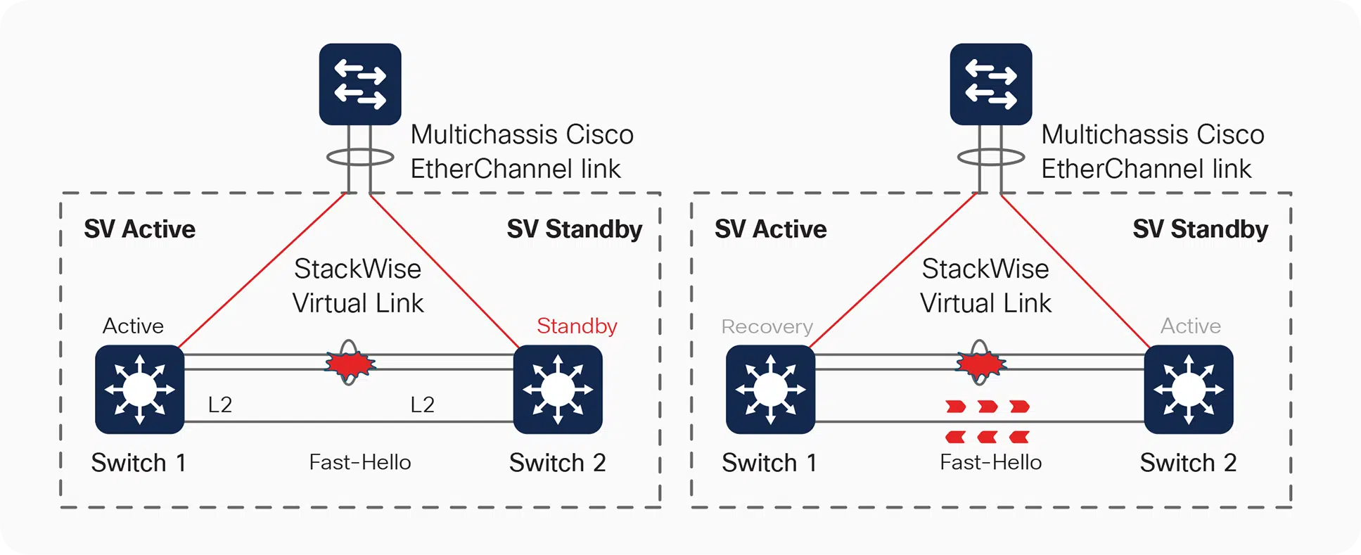
All SVL Links Fail While Both Switches Are Still Running
For this scenario, the independent Fast Hello DAD link remains operational. Both switches are alive, but both 100G SVL members have failed.
The original Standby, SW2, loses its peer communication and assumes the Active role. SW1 is still running, so the system temporarily has two Active members with a shared logical identity. DAD detects the condition, allowing SW1 to enter recovery mode and isolate its ordinary network interfaces. SW2 continues as Active.
For this C9500 release family, recovery preserves SVL/DAD interfaces. Once the SVL is repaired, the isolated switch normally reloads and returns as Standby; a configuration option can disable that automatic recovery reload. Check the deployed setting before writing the recovery procedure.
The restored cable is only the first recovery milestone. Confirm that the returning member is synchronized, its network interfaces are usable, and the original traffic paths and redundancy have been restored.
A DAD Link Fails While SVL Remains Up
A failed DAD link, by itself, does not mean the two switches have become Active. With SVL communication healthy, the pair can retain its existing roles and forwarding paths. It has lost that detection path, however, so this is a degraded protection state requiring repair.
Another configured, working DAD mechanism may still provide detection. If all effective DAD paths are unavailable and the entire SVL subsequently fails, do not assume the isolation sequence above will occur. Both live members may operate with the same logical identity, affecting network stability. Cisco’s troubleshooting guidance specifically checks DAD health when expected recovery mode is absent.
| Failure condition | Roles and forwarding impact | Recovery focus |
|---|---|---|
| One SVL member fails; another works | Pair remains connected with less interconnect capacity | Repair the member; check load on the survivor |
| One MEC member fails | Remaining bundle members may carry traffic; local paths can change | Check bundle requirements and SVL load |
| Standby chassis fails | Active remains; failed chassis ports disappear | Restore the member and redundancy |
| Active chassis fails | Healthy Standby takes control; failed chassis ports disappear | Validate new Active and surviving services |
| All SVL members fail; DAD works; both chassis live | Dual-active detection isolates the original Active | Repair SVL and verify controlled rejoin |
| DAD fails; SVL works | Roles normally remain; detection protection is reduced | Restore DAD before another failure compounds risk |
| All SVL and effective DAD paths fail; both chassis live | Dual-active isolation cannot be relied upon | Follow the reviewed isolation and recovery procedure |
How Do You Size and Protect Cisco StackWise Virtual Links?
Size Cisco StackWise Virtual links for traffic that crosses between chassis during normal operation and required failure scenarios, and separate SVL and DAD routes to reduce shared physical failure risks.
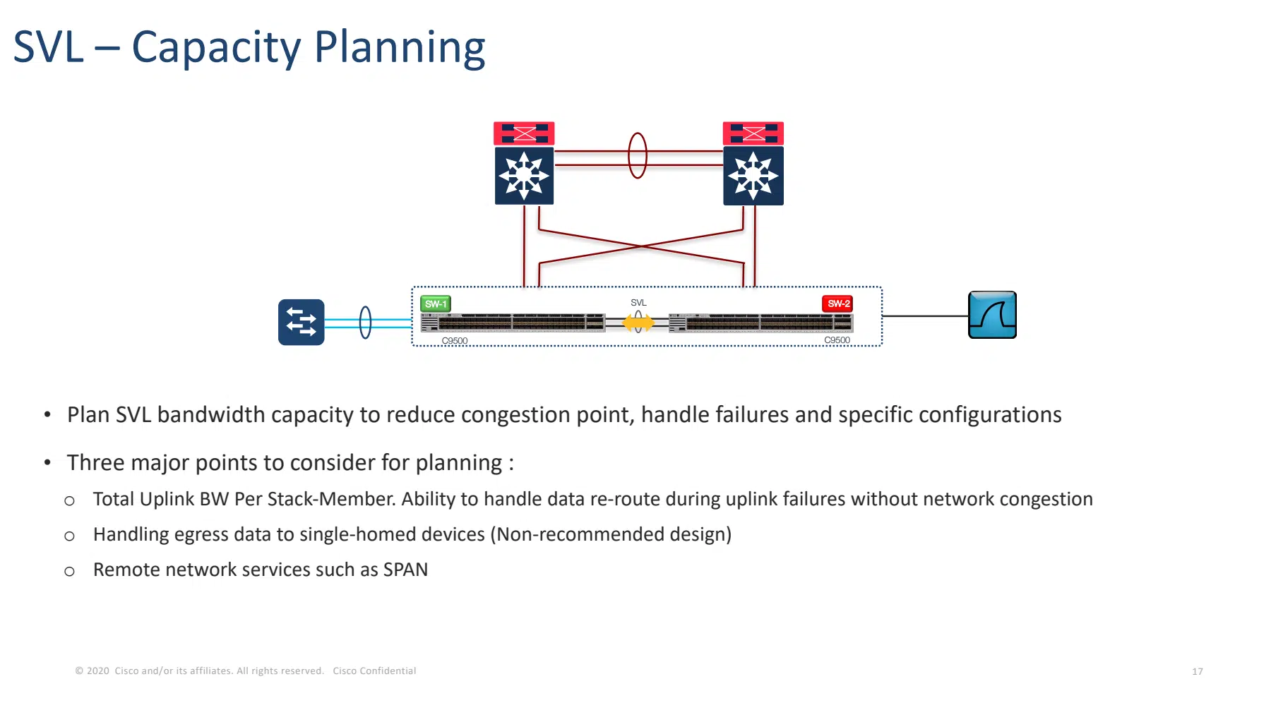
Size for Traffic That Moves During a Failure
Adding every access-port speed produces a poor estimate if most packets leave locally; measuring only the normal SVL average can miss a serious failure-state bottleneck.
For the teaching example, the nominal arithmetic is:
- Two working 100G members: 200 Gbps aggregate line rate in each direction.
- One working 100G member: 100 Gbps line rate in each direction.
Those values describe the links. They do not promise application throughput: encapsulation, packet sizes, traffic distribution, hashing, and burst behavior affect usable capacity. A single hashed flow does not automatically combine both links into a 200G path.
| State to assess | Traffic assumption to examine | Capacity question |
|---|---|---|
| Normal operation | Local MEC exits available; remote service traffic crosses SVL | What crosses in each direction during busy periods? |
| One SVL member lost | Similar demand on fewer interconnect members | Can the surviving 100G member carry required traffic? |
| SW1 loses its local upstream MEC exits | Traffic entering SW1 may need SW2’s upstream exit | Can the SVL and surviving upstream links absorb the redirected load? |
For a numerical exercise, assume 25 Gbps of existing SW1-to-SW2 traffic and 90 Gbps of separate traffic that must move from SW1 to SW2 when SW1 loses its local upstream exits. These are hypothetical busy-period demands in the same direction, with no traffic counted twice. The resulting 115 Gbps demand fits below the two-link nominal aggregate but exceeds a single 100G member:
| Hypothetical condition | SW1-to-SW2 demand | Nominal SVL capacity in that direction | Design implication |
|---|---|---|---|
| Normal operation | 25 Gbps | 200 Gbps | Check distribution and bursts despite aggregate headroom. |
| One SVL member fails | 25 Gbps | 100 Gbps | Demand is below the remaining nominal capacity. |
| Local upstream exits fail; both SVL members work | 115 Gbps | 200 Gbps | Aggregate headroom exists; per-member loading still matters. |
| Local upstream exits and one SVL member fail | 115 Gbps | 100 Gbps | Capacity is insufficient even before overhead. |
The last row combines two failures. Include it when that combination is part of the required protection target. Even with both links working, 115 Gbps spread across multiple flows is not a guarantee of balanced hashing or freedom from congestion.
Also account for services such as remote monitoring traffic where relevant. Record the combinations of failures the business expects the design to withstand, then assess those combinations explicitly. There is no universal SVL-to-uplink bandwidth ratio that replaces that traffic model.
Place SVL and DAD Links Across Appropriate Failure Domains
A separate DAD port is only one part of independence. If every inter-switch fiber passes through one vulnerable patching location, a single physical event could remove SVL and DAD together.
Review actual cable routes, patch panels, power, and maintenance access. Use diverse paths where practical, and document shared points that remain. On modular platforms, also consider which line cards host the connections and whether the proposed separation is supported.
Distance follows the supported connection and transceiver requirements. A link between buildings still needs a supported direct inter-switch design; available fiber does not make arbitrary transport arrangements valid. Check the specific optics, speeds, and port restrictions before treating physical separation as an availability benefit.
What Hardware, Software, and Licenses Does Cisco StackWise Virtual Require?
Cisco StackWise Virtual requires a supported hardware pairing and compatible software, licensing, and port configuration; for this C9500 example, the model, IOS XE version, Network Advantage level, and SDM template must match. A familiar family name or a successful link-up is not a substitute for feature compatibility.
Use supported equal-speed SVL members for the C9500-24Y4C example. The 100G SVL and 10G DAD connections serve different purposes and do not need to share one speed. The model’s supported interfaces accommodate this conceptual arrangement.
| Platform scope | Checks that change the design |
|---|---|
| C9500-24Y4C example | Exact maintenance release, matched software/license/SDM, native supported ports, transceivers, and SVL-member speed |
| Other C9500 models | Port eligibility and adapter/breakout restrictions vary; for example, C9500-32C restricts SVL/DAD to ports 1–16 |
| C9400 | Chassis, supervisor, symmetrical slots, selected line cards, and licensing conditions |
| C9600 | Supervisor generation, line-card combinations, slot placement, and intended redundancy mode |
The C9400 IOS XE 17.18 guide restricts StackWise Virtual to one supervisor per chassis and identifies an additional upgrade license for C9400-SUP-1. The C9600 has a separate quad-supervisor RPR design; those rules are not interchangeable.
C9500X and C9600X Supervisor 2 also have implementation differences, including LACP/IS-IS in place of classic LMP/SDP for the interconnect infrastructure. Their supported speeds and change procedures need separate checks. For example, C9600X Supervisor 2 permits dynamic SVL/DAD member changes once operating in SVL mode.
These references were checked on September 14, 2026. The table is an implementation index for the covered Catalyst families, not an exhaustive list of all current Cisco switching platforms.
How Do You Deploy and Verify Cisco StackWise Virtual?
Deploy Cisco StackWise Virtual by confirming platform prerequisites, planning SVL, DAD, and network connections, and following the release-specific conversion procedure; then verify member roles, SSO readiness, link health, and service behavior.
Prepare the Pair and Plan the Conversion
Turn the conceptual topology into a reviewed implementation plan before changing switch mode:
- Record the existing state. Save configurations, hardware identities, interface assignments, routing relationships, and service dependencies. Confirm console or out-of-band access to both chassis.
- Resolve prerequisites. Select the exact software build and optics, check support, and align the required platform settings.
- Map every connection. Identify SVL members, the independent DAD path, MEC members, and single-homed services. Specify what stays reachable during each conversion stage.
- Plan configuration ownership and conversion. Decide the intended logical configuration and member identities. Follow the exact platform’s conversion procedure, including required saves and reloads.
- Define acceptance and rollback. Set service checks and a clear stopping point before the maintenance window begins.
Do not assume a procedure for changing links on a newer platform applies to first-time conversion on the example pair. A version-scoped plan should state precisely which action requires a reload.
Verify Roles, Links, Forwarding, and Failure Behavior
Verification should establish readiness and service behavior, not just that both chassis booted. Cisco’s troubleshooting documentation provides the relevant state and link checks; the following table summarizes their purpose without presenting fabricated device output.
| Check | Inspection | Acceptance question |
|---|---|---|
| Membership | show switch | Are both expected members present and ready, with the intended roles? |
| Redundancy | show redundancy | Is SSO operational and the peer ready for control-plane takeover? |
| Interconnect | show stackwise-virtual link | Are all planned SVL members up with healthy protocol state? |
| Detection | show stackwise-virtual dual-active-detection | Is the planned Fast Hello path operational? |
| Network attachment | MEC membership, interfaces, and neighbor state | Are the intended links actually participating? |
| Services | Path-specific application checks and counters | Do local and cross-chassis services work as designed? |
Link state and protocol state are separate observations. A lit optic alone does not establish that a member has joined a healthy SVL. Likewise, an operational Port-Channel may conceal a missing member or reduced redundancy.
In a controlled test environment, exercise a single member-link failure, chassis/role changes, DAD-only loss, and SVL-loss recovery as separate cases. Restore the healthy baseline between tests, record application impact, and confirm the remaining detection path before testing complete SVL loss.
How Do You Plan Cisco StackWise Virtual ISSU and Recovery?
Plan Cisco StackWise Virtual ISSU around an exact supported source-to-target upgrade path, operational redundancy, service checks, and a defined rollback decision point. “The platform supports ISSU” does not establish that a particular upgrade is supported. Check Cisco’s current matrix for the platform and redundancy mode, along with release-specific restrictions.
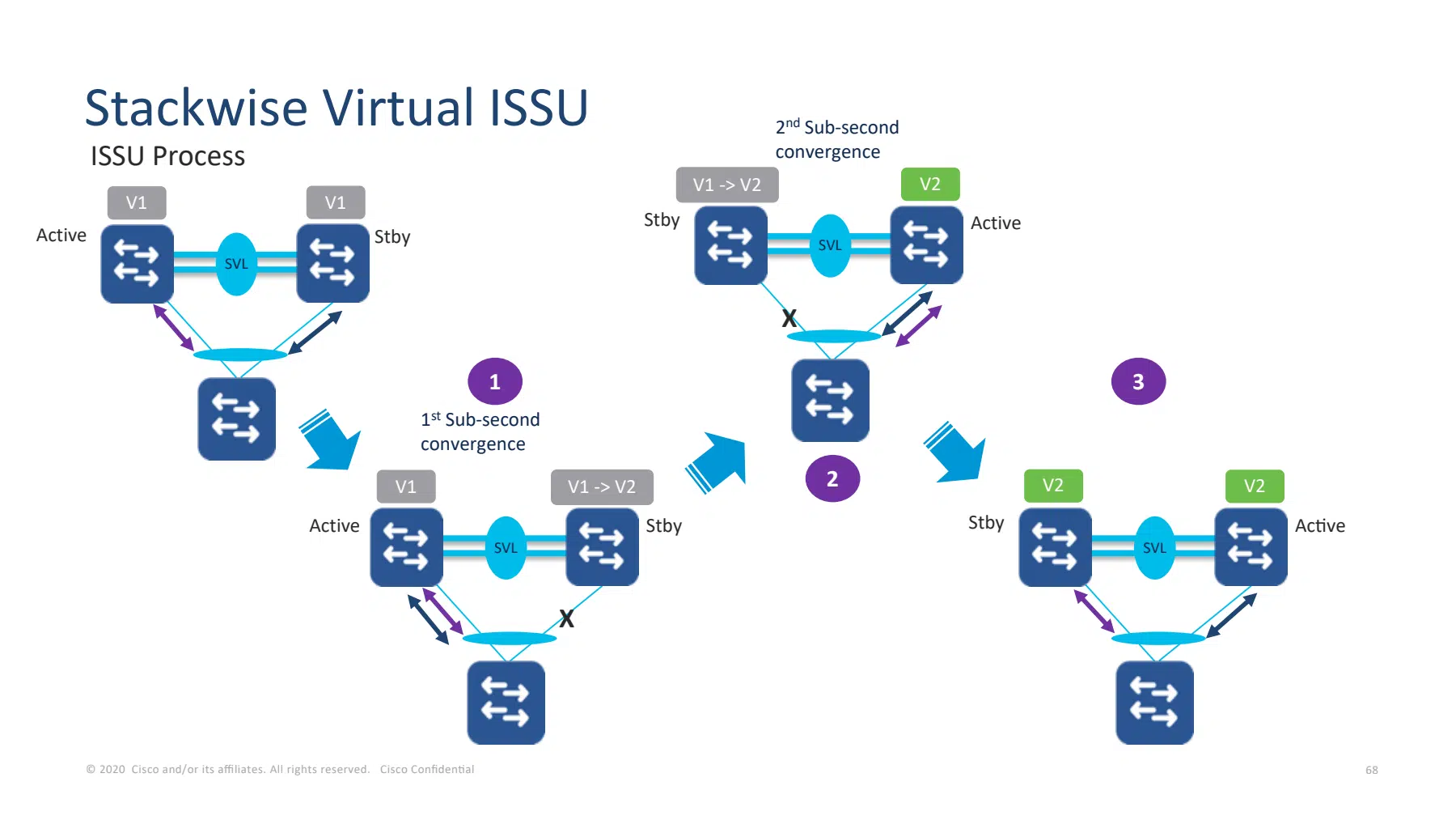
For supported C9500 StackWise Virtual paths, the process upgrades the Standby side and uses a role transition while the other side is upgraded. The platform guide requires install mode and NSF and recommends a maintenance window. Single-homed devices lose connectivity when their attached chassis reboots, even when the pair follows a supported ISSU procedure.
| Maintenance stage on a supported path | What the team must verify |
|---|---|
| Prepare software and confirm eligibility | Exact source/target path, install mode, redundancy readiness and recovery options |
| Upgrade and restart the Standby side | The remaining chassis carries required services; single-homed attachments to the restarting side are interrupted |
| Transition roles and upgrade the former Active | Working alternate paths and sufficient capacity remain during the transition |
| Verify and complete the documented workflow | Both versions, synchronized roles, SVL/DAD health, MEC membership and application checks |
Before maintenance, record the supported path, redundancy health, image availability, service checks, and rollback decision point. Understand the chosen workflow’s commit and rollback behavior; an available rollback option does not make every downgrade an ISSU operation. Keep an independent way to reach the equipment if the logical management path is unavailable.
Afterward, verify both software versions, SSO readiness, every SVL and DAD member, MEC participation, and the single-homed service. Device replacement and rejoining a switch isolated by DAD are different recovery tasks and need their own procedures.
The design is ready for review when the team can trace important traffic in normal and failure states, identify which detection path remains after a fault, and show that the surviving network has enough capacity. If the shared logical system does not fit the required failure boundaries, return to the StackWise and StackWise Virtual design comparison before selecting hardware.
What Else Should Engineers Know About Cisco StackWise Virtual?
Cisco StackWise Virtual uses SVL, DAD, and MEC for different functions, so evaluate interconnect capacity, dual-active protection, endpoint paths, and upgrade support separately.
Does the StackWise Virtual Link carry only control traffic?
No. The SVL carries control and synchronization traffic plus user traffic that needs the peer chassis. A packet entering SW1 for an endpoint attached only to SW2 must cross it; traffic with an eligible local exit may remain local.
Can a DAD link replace a failed SVL?
No. Fast Hello DAD detects dual activity; it does not replace SVL synchronization or carry displaced user traffic. Cisco requires SVL and Fast Hello DAD to use different ports.
What happens if the DAD link fails but SVL stays up?
With SVL healthy, a DAD-only failure normally leaves roles and forwarding unchanged. Protection is degraded: verify any remaining DAD mechanism and repair the failed path, because complete SVL loss without working DAD can prevent safe isolation.
Does MEC send every packet across the SVL?
No. A MEC favors eligible member links on the switch where traffic enters, including the control-plane Standby. Traffic crosses the SVL when it needs an exit on the peer, such as after all local MEC exits fail; return traffic can follow a different physical path.
Do two 100G SVL links give a single flow 200 Gbps?
No. The arithmetic gives 200 Gbps of nominal aggregate capacity in each direction, while a hashed flow uses one member. Actual performance depends on overhead, traffic distribution, and congestion; one failed member leaves 100 Gbps nominal capacity. Cisco also warns that hashing can overload one SVL member despite available aggregate capacity.
How does StackWise Virtual recover after all SVL links fail?
With both chassis alive and independent DAD working, the Standby becomes Active and the original Active isolates its ordinary network ports. In the C9500 example, the isolated switch normally reloads and rejoins as Standby after SVL repair; automatic recovery reload can be disabled. Without working DAD, do not assume isolation occurs.
Does StackWise Virtual ISSU guarantee zero downtime?
No. A supported ISSU path preserves forwarding through the available chassis, but a device attached only to the rebooting chassis temporarily loses connectivity. Verify the exact upgrade path, install mode, NSF, and working alternate connections; Cisco recommends a maintenance window. Dual-homing is necessary for continuity through a chassis reboot, not a blanket application guarantee.
Can different Catalyst 9500 models form one StackWise Virtual pair?
No. Cisco's IOS XE 17.18 guide requires the same switch model, software version, license level, and SDM template. A C9500-24Y4C therefore cannot pair with a C9500-48Y4C; belonging to the same Catalyst family does not establish compatibility.